

一、简介
本章聚焦于BGP相关的各个知识点,具体包括BGP邻居关系,BGP认证功能,BGP自动和手动路由聚合,各种常见的BGP路由属性分析,路由反射器、路由黑洞问题,BGP联盟,BGP路由的过滤、引入和衰减,BGP缺省路由,BGP网络的监测、调试和排障。
二、BGP邻居
2.1 原理概述
路由协议通常分为内部网关协议(IGP:Interior Gateway Protocol)和外部网关协议(EGP:Exterior Gateway Protocol)两大类。一般来说,IGP用于自治系统AS(Autonomous System)内部,EGP用于AS之间。
BGP虽然是一种动态路由协议,但它实际上本身并不产生路由、不发现路由、不计算路由,其主要功能是完成最佳路由的选择并在BGP邻居之间进行最佳路由的传递。BGP选择了TCP作为其传输协议,端口号为179.
BGP支持无类域间路由CIDR(Classes Inter-Domain Routing),并且采用了触发增量更新方式,这大大减少了BGP在传播路由信息时所占用的带宽,特别适用于在互联网上传播大量的路由信息。
BGP提供了丰富的路由属性(Attrbute),通过对这些属性的操作和控制,BGP能够非常容易地实现丰富而灵活的路由策略。BGP还具有良好的扩展性,支持Multicast、VPN、IPv6等多种特性。
BGP的邻居关系分为IBGP(Internal BGP)和EBGP(External BGP)两种:当两台BGP路由器位于同一AS时(AS编号相同),它们的邻居关系为IBGP邻居关系;当两台BGP路由器位于不同的AS时(AS编号不同),它们的邻居关系为EBGP邻居关系,BGP没有自动建立邻居关系的能力,邻居关系必须通过手动配置来建立。
2.2 BGP邻居配置实验
2.2.1 实验目的
1、理解BGP协议的应用场景 2、理解IBGP与EBGP邻居的概念 3、配置IBGP与EBGP邻居关系
2.2.2 实验内容
R1和R2属于同一个运营商网络,AS编号为100,R1与R2之间的邻居关系为IBGP邻居关系。R3属于另一个运营商网络,AS编号为200,R3与R2之间的邻居关系为EBGP邻居关系。本实验,路由器将分别采用物理接口和LoopBack接口来进行IBGP和EBGP邻居关系的建立。
2.2.3 实验拓扑
2.2.4 实验编址表
| 设备 | 接口 | IP地址 | 子网掩码 | 默认网关 |
|---|---|---|---|---|
| R1(AR2220) | GE0/0/0 | 10.0.12.1 | 255.255.255.0 | N/A |
| R1(AR2220) | GE0/0/1 | 10.0.21.1 | 255.255.255.0 | N/A |
| R1(AR2220) | LoopBack 0 | 10.0.1.1 | 255.255.255.255 | N/A |
| R2(AR2220) | GE0/0/0 | 10.0.12.2 | 255.255.255.0 | N/A |
| R2(AR2220) | GE0/0/1 | 10.0.23.2 | 255.255.255.0 | N/A |
| R2(AR2220) | GE0/0/2 | 10.0.21.2 | 255.255.255.0 | N/A |
| R2(AR2220) | GE4/0/0 | 10.0.32.2 | 255.255.255.0 | N/A |
| R2(AR2220) | LoopBack 0 | 10.0.2.2 | 255.255.255.255 | N/A |
| R3(AR2220) | GE0/0/0 | 10.0.23.3 | 255.255.255.0 | N/A |
| R3(AR2220) | GE0/0/1 | 10.0.32.3 | 255.255.255.0 | N/A |
| R3(AR2220) | LoopBack 0 | 10.0.3.3 | 255.255.255.255 | N/A |
| ### 2.2.5 实验步骤 | ||||
| #### 2.2.5.1 基本配置 | ||||
| 根据实验编制表进行基本配置,并使用ping命令检测R1和R2之间的连通性。 | ||||
| #### 2.2.5.2 配置IBGP邻居 | ||||
| ##### 2.2.5.2.1 使用物理口创建邻居 | ||||
| 1、在R1和R2上使用直连物理口来配置IBGP邻居关系。为了实现链路冗余,R1与R2之间部署了两条链路,当其中一条物理链路出现故障时,另一条物理链路可以提供连通性。 |
[R1]bgp 100
[R1-bgp]router-id 10.0.1.1
[R1-bgp]peer 10.0.12.2 as-number 100
[R1-bgp]peer 10.0.21.2 as-number 100

[R2]bgp 100
[R2-bgp]router-id 10.0.2.2
[R2-bgp]peer 10.0.12.1 as-number 100
[R2-bgp]peer 10.0.21.1 as-number 100
2、配置完成后,在R2上使用dis bgp peer命令查看BGP邻居关系。观察到,R2有两个BGP邻居,其中AS编号为100,与R2自己的AS编号相同,因此R2和R1为IBGP邻居,当前邻居状态为Established,表明邻居关系已完全建立。
[R2]dis bgp peer

 BGP local router ID : 10.0.2.2
 Local AS number : 100
 Total number of peers : 2        Peers in established state : 2

  Peer            V          AS  MsgRcvd  MsgSent  OutQ  Up/Down       State Pre
fRcv

  10.0.12.1       4         100        2        2     0 00:00:11 Established
   0
  10.0.21.1       4         100        2        2     0 00:00:03 Established
3、在R1上将Loopback 0接口地址通告到BGP进程中。
[R1]bgp 100
[R1-bgp]network 10.0.1.1 32
4、配置完成后,在R2上查看BGP路由表,观察到R2的BGP路由表中包含了两条去往10.0.1.1/32的路由,下一跳分别为10.0.12.1和10.0.21.1。(*代表下一跳可达,>代表最优路由)
[R2]dis bgp routing-table

 BGP Local router ID is 10.0.2.2
 Status codes: * - valid, > - best, d - damped,
               h - history,  i - internal, s - suppressed, S - Stale
               Origin : i - IGP, e - EGP, ? - incomplete

 Total Number of Routes: 2
      Network            NextHop        MED        LocPrf    PrefVal Path/Ogn

 *>i  10.0.1.1/32        10.0.12.1       0          100        0      i
 * i                     10.0.21.1       0          100        0      i
2.2.5.2.2 使用LoopBack口创建邻居
1、为了使R1的LoopBack口和R2的LoopBack口建立起TCP会话,需要在R1和R2上配置到达对方LoopBack 0接口的静态路由。
[R1]ip route-static 10.0.2.2 32 10.0.12.2
[R1]ip route-static 10.0.2.2 32 10.0.21.2

[R2]ip route-static 10.0.1.1 32 10.0.12.1
[R2]ip route-static 10.0.1.1 32 10.0.21.1
2、删除之前采用物理接口配置IBGP邻居的命令,并使用LoopBack 0接口重新建立IBGP邻居关系。
[R1]bgp 100
[R1-bgp]undo peer 10.0.12.2
[R1-bgp]undo peer 10.0.21.2
[R1-bgp]peer 10.0.2.2 as-number 100

[R2]bgp 100
[R2-bgp]undo peer 10.0.12.1
[R2-bgp]undo peer 10.0.21.1
[R2-bgp]peer 10.0.1.1 as-number 100
3、配置完成后,在R1上查看BGP邻居关系。观察到R1和R2的邻居关系停留在Active状态,说明未成功建立起IBGP邻居关系。这是因为R1向R2或R2向R1发送BGP报文的源IP地址和指定的邻居地址不一致,从而导致R1和R2无法建立起邻居关系。
[R1-bgp]dis bgp peer

 BGP local router ID : 10.0.1.1
 Local AS number : 100
 Total number of peers : 1        Peers in established state : 0

  Peer            V          AS  MsgRcvd  MsgSent  OutQ  Up/Down       State Pre
fRcv

  10.0.2.2        4         100        0        0     0 00:01:30      Active
4、针对上面问题,使用peer 10.0.2.2 connect-interface LoopBack 0 命令强制指定路由器发送BGP报文时所使用的源IP地址。
[R1]bgp 100
[R1-bgp]peer 10.0.2.2 connect-interface LoopBack 0

[R2]bgp 100
[R2-bgp]peer 10.0.1.1 connect-interface LoopBack 0
5、配置完成后,在R2上查看BGP邻居关系。目前只存在10.0.1.1一个BGP邻居关系。
[R2]dis bgp peer

 BGP local router ID : 10.0.2.2
 Local AS number : 100
 Total number of peers : 1        Peers in established state : 1

  Peer            V          AS  MsgRcvd  MsgSent  OutQ  Up/Down       State Pre
fRcv

  10.0.1.1        4         100        3        2     0 00:00:12 Established
6、查看R2的BGP路由表。观察到,只有一条去往10.0.1.1/32的路由,下一跳为10.0.1.1。
[R2]dis bgp routing-table

 BGP Local router ID is 10.0.2.2
 Status codes: * - valid, > - best, d - damped,
               h - history,  i - internal, s - suppressed, S - Stale
               Origin : i - IGP, e - EGP, ? - incomplete

 Total Number of Routes: 1
      Network            NextHop        MED        LocPrf    PrefVal Path/Ogn

   i  10.0.1.1/32        10.0.1.1        0          100        0      i
7、再查看R2的路由表,观察到,R2去往10.0.1.1的路由有两条,下一跳分别为10.0.12.1 、10.0.21.1。形成冗余链路。
[R2]dis ip routing-table
Route Flags: R - relay, D - download to fib
------------------------------------------------------------------------------
Routing Tables: Public
         Destinations : 18       Routes : 19

Destination/Mask    Proto   Pre  Cost      Flags NextHop         Interface

       10.0.1.1/32  Static  60   0          RD   10.0.12.1       GigabitEthernet
0/0/0
                    Static  60   0          RD   10.0.21.1       GigabitEthernet
0/0/2
       10.0.2.2/32  Direct  0    0           D   127.0.0.1       LoopBack0
      10.0.12.0/24  Direct  0    0           D   10.0.12.2       GigabitEthernet
0/0/0
      10.0.12.2/32  Direct  0    0           D   127.0.0.1       GigabitEthernet
0/0/0
    10.0.12.255/32  Direct  0    0           D   127.0.0.1       GigabitEthernet
0/0/0
      10.0.21.0/24  Direct  0    0           D   10.0.21.2       GigabitEthernet
0/0/2
      10.0.21.2/32  Direct  0    0           D   127.0.0.1       GigabitEthernet
0/0/2
    10.0.21.255/32  Direct  0    0           D   127.0.0.1       GigabitEthernet
0/0/2
      10.0.23.0/24  Direct  0    0           D   10.0.23.2       GigabitEthernet
0/0/1
      10.0.23.2/32  Direct  0    0           D   127.0.0.1       GigabitEthernet
0/0/1
    10.0.23.255/32  Direct  0    0           D   127.0.0.1       GigabitEthernet
0/0/1
      10.0.32.0/24  Direct  0    0           D   10.0.32.2       GigabitEthernet
4/0/0
      10.0.32.2/32  Direct  0    0           D   127.0.0.1       GigabitEthernet
4/0/0
    10.0.32.255/32  Direct  0    0           D   127.0.0.1       GigabitEthernet
4/0/0
      127.0.0.0/8   Direct  0    0           D   127.0.0.1       InLoopBack0
      127.0.0.1/32  Direct  0    0           D   127.0.0.1       InLoopBack0
127.255.255.255/32  Direct  0    0           D   127.0.0.1       InLoopBack0
255.255.255.255/32  Direct  0    0           D   127.0.0.1       InLoopBack0
说明:使用LoopBack接口建立BGP邻居关系与使用物理接口来建立邻居关系相比,前者具有更好的稳定性,且能够减少设备资源的开销.
2.2.5.3 配置EBGP邻居
1、在R2和R3上使用Loopback 0接口来建立EBGP邻居关系
[R2]bgp 100
[R2-bgp]peer 10.0.3.3 as 200
[R2-bgp]peer 10.0.3.3 connect-interface loop 0

[R3]bgp 200
[R3-bgp]router-id 10.0.3.3
[R3-bgp]peer 10.0.2.2 as 100
[R3-bgp]peer 10.0.2.2 connect-interface loop 0
2、配置完成后,在R3上查看BGP邻居关系。观察到,R2和R3的邻居状态一直停留在Idle状态。说明邻居关系未能正常建立。这是因为BGP邻居关系建立的前提条件是能够建立起TCP会话。
[R3]dis bgp peer

 BGP local router ID : 10.0.3.3
 Local AS number : 200
 Total number of peers : 1        Peers in established state : 0

  Peer            V          AS  MsgRcvd  MsgSent  OutQ  Up/Down       State Pre
fRcv

  10.0.2.2        4         100        0        0     0 00:01:22        Idle
3、在R2和R3上配置到达对方LoopBack0接口的静态路由。
[R2]ip route-static 10.0.3.3 32 10.0.23.3
[R2]ip route-static 10.0.3.3 32 10.0.32.3

[R3]ip route-static 10.0.2.2 32 10.0.23.2
[R3]ip route-static 10.0.2.2 32 10.0.32.2
4、继续在R3上查看BGP邻居关系。观察到,邻居关系仍然没有建立起来。这是因为在默认情况下,EBGP邻居之间在发送BGP报文时,TTL值为1,所以EBGP默认要求邻居之间必须物理直连。但是,当R2和R3使用LoopBack 0接口建立邻居关系时,由于使用的不是物理直连的接口,所以TTL值会被多减一次,成为0,最终BGP报文会丢弃,导致邻居关系无法建立。
[R3]dis bgp peer

 BGP local router ID : 10.0.3.3
 Local AS number : 200
 Total number of peers : 1        Peers in established state : 0

  Peer            V          AS  MsgRcvd  MsgSent  OutQ  Up/Down       State Pre
fRcv

  10.0.2.2        4         100        1        0     0 00:00:28        Idle
5、在R2和R3上使用命令peer ebgp-max-hop 2,配置BGP报文的TTL值为2.
[R2-bgp]peer 10.0.3.3 ebgp-max-hop 2

[R3-bgp]peer 10.0.2.2 ebgp-max-hop 2
6、继续在R3上查看BGP邻居关系。观察到,EBGP邻居关系成功建立起来。
[R3-bgp]dis bgp peer

 BGP local router ID : 10.0.3.3
 Local AS number : 200
 Total number of peers : 1        Peers in established state : 1

  Peer            V          AS  MsgRcvd  MsgSent  OutQ  Up/Down       State Pre
fRcv

  10.0.2.2        4         100        2        2     0 00:00:10 Established
   0
说明:在实际场景中,通常使用LoopBack接口来建立IBGP邻居关系,使用物理接口建立EBGP邻居关系。
2.3 思考
BGP协议选择了TCP协议作为其传输协议,这样做有什么好处?OSPF协议也是以TCP协议作为其传输协议吗? 答:(1)TCP是一种面向连接的、稳定可靠的传输层协议。(2)OSPF本身提供主从协商机制,可以保证可靠的传输,另外全网路由器保持着同样的一个LSDB(链路状态数据库),当拓扑发生变化时,需要携带的变更信息较少,通过IP协议即可完成.
三、BGP认证功能
3.1 原理概述
BGP是一种运行在AS之间的动态路由协议,具备强大的路径选择能力,这也使得BGP协议能够管理超大型网络。对于超大型网络来说,路由的稳定性和安全性特别重要。在实际部署各种路由协议时,通常会配置认证功能,BGP更是如此。所谓认证,就是指路由器对路由信息来源的可靠性及路由信息本身的完整性进行检测的机制。
BGP支持简单的密码认证方式,也支持安全性更高的MD5认证方式。如果是MD5认证方式,路由器会根据BGP报文的某些字段和密钥计算出一个128比特的散列值,然后将BGP报文连同散列值发送给邻居。邻居路由器收到之后,会在本地基于接收到的BGP报文和相同的密钥再进行一次Hash运算。如果计算出的散列值与接收到的散列值相同,则认证通过,邻居关系能够正常建立;如果不同,则认证不通过,邻居关系就不会建立,且所收到的BGP报文会丢弃。
BGP认证方式有两种:一种是基于单一密钥的BGP认证功能,通常会使用Cipher方式,使得存储于配置文件的密钥不会以明文方式显示,密钥的安全性更高;另外一种是基于keychain的BGP认证,可以实现密钥的周期性更换,并且对众多的密钥进行集中管理。使用keychain的方式可以定义密钥的存活期,但应保证设备的系统时间一致,避免认证失败。在keychain方式下定义密钥的存活期分为Absolute与Periodic两种模式。Absolute模式下,密钥key的有效时间为一个绝对时间段。Periodic模式下,一个Key的有效时间为周期性的一段时间,分为Daily、Monthly、Weekly和Yearly等。
3.2 BGP认证配置实验
3.2.1 实验目的
1、掌握基于单一密钥的BGP认证功能的配置 2、掌握基于Keychain的BGP认证功能的配置
3.2.2 实验内容
本实验使用了3台路由器,R1和R2属于ISP-A的网络,AS编号为100,R3属于ISP-B网络,AS编号为200.R1与R2建立IBGP邻居关系,R2和R3建立EBGP邻居关系。为了保证BGP邻居之间发送的BGP路由信息的完整性,决定在BGP邻居之间配置认证功能。
3.2.3 实验拓扑

3.2.4 实验编址表
| 设备 | 接口 | IP地址 | 子网掩码 | 默认网关 |
|---|---|---|---|---|
| R1(AR2220) | GE0/0/0 | 10.0.12.1 | 255.255.255.0 | N/A |
| R1(AR2220) | LoopBack 0 | 10.0.1.1 | 255.255.255.255 | N/A |
| R2(AR2220) | GE0/0/0 | 10.0.12.2 | 255.255.255.0 | N/A |
| R2(AR2220) | GE0/0/1 | 10.0.23.2 | 255.255.255.0 | N/A |
| R2(AR2220) | LoopBack 0 | 10.0.2.2 | 255.255.255.255 | N/A |
| R3(AR2220) | GE0/0/0 | 10.0.23.3 | 255.255.255.0 | N/A |
| R3(AR2220) | LoopBack 0 | 10.0.3.3 | 255.255.255.255 | N/A |
| ### 3.2.5 实验步骤 | ||||
| #### 3.2.5.1 基本配置 | ||||
| 根据实验编制表进行基本配置,并使用ping命令检测R1和R2之间的连通性。 | ||||
| #### 3.2.5.2 配置BGP路由协议 | ||||
| 1、R1和R2属于AS 100,R3属于AS 200,使用直连的物理接口的IP地址来建立BGP邻居关系。 |
[R1]bgp 100
[R1-bgp]router-id 10.0.1.1
[R1-bgp]peer 10.0.12.2 as 100

[R2]bgp 100
[R2-bgp]router-id 10.0.2.2
[R2-bgp]peer 10.0.12.1 as 100
[R2-bgp]peer 10.0.23.3 as 200

[R3]bgp 200
[R3-bgp]router-id 10.0.3.3
[R3-bgp]peer 10.0.23.2 as 100
2、配置完成后,在R2上查看BGP邻居关系。观察到,邻居关系均已建立完毕。
[R2]dis bgp peer

 BGP local router ID : 10.0.2.2
 Local AS number : 100
 Total number of peers : 2        Peers in established state : 2

  Peer            V          AS  MsgRcvd  MsgSent  OutQ  Up/Down       State Pre
fRcv

  10.0.12.1       4         100        3        3     0 00:01:25 Established
   0
  10.0.23.3       4         200        2        4     0 00:00:19 Established
3.2.5.3 配置基于单一密钥的BGP认证功能
1、分别在R1、R2、R3上配置BGP认证功能
[R1]bgp 100
[R1-bgp]peer 10.0.12.2 password simple huawei

[R2]bgp 100
[R2-bgp]peer 10.0.12.1 password simple huawei123
[R2-bgp]peer 10.0.23.3 password simple huawei

[R3]bgp 200
[R3-bgp]peer 10.0.23.2 password cipher huawei
2、配置完成后,观察到R2和R3邻居状态为Established,与R1的邻居状态为Connect,说明了R2与R3建立了正常的邻居关系,但是与R1未能建立起正常的邻居关系。这是因为R1使用的密钥和R2使用的密钥不一致,无法进行正确的认证,所以建立不了邻居关系。虽然R2使用的Simple方式,R3使用的是Cipher方式,但这并不影响R2和R3之间的邻居关系的建立。它两的区别仅仅在于一个是明文一个是密文。
[R1]dis bgp peer

 BGP local router ID : 10.0.1.1
 Local AS number : 100
 Total number of peers : 1        Peers in established state : 0

  Peer            V          AS  MsgRcvd  MsgSent  OutQ  Up/Down       State Pre
fRcv

  10.0.12.2       4         100        0        0     0 00:00:47     Connect

[R2]dis bgp peer

 BGP local router ID : 10.0.2.2
 Local AS number : 100
 Total number of peers : 2        Peers in established state : 1

  Peer            V          AS  MsgRcvd  MsgSent  OutQ  Up/Down       State Pre
fRcv

  10.0.12.1       4         100        0        0     0 00:00:34     Connect
   0
  10.0.23.3       4         200       10       12     0 00:08:27 Established
3、在R2上将配置错误的密钥进行更正,然后再次查看R2的BGP邻居关系。观察到,密钥修正之后,R2和R1之间的邻居关系已经正常建立。
[R2-bgp]peer 10.0.12.1 password simple huawei

[R2]dis bgp peer

 BGP local router ID : 10.0.2.2
 Local AS number : 100
 Total number of peers : 2        Peers in established state : 2

  Peer            V          AS  MsgRcvd  MsgSent  OutQ  Up/Down       State Pre
fRcv

  10.0.12.1       4         100        2        2     0 00:00:02 Established
   0
  10.0.23.3       4         200       18       20     0 00:16:19 Established
   0
3.2.5.4 配置基于Keychain的BGP认证功能
1、在R1和R2上配置基于Keychain的BGP认证功能,Key-ID为1,Key-String为huawei,选用Periodic Daily模式,每天8:00-18:00使用Key-ID 1对发送的BGP报文做Hash运算,每天8:00-18:00使用Key-ID 1对接收到的BGP报文进行认证。
[R1]keychain key mode periodic daily
[R1-keychain]key-id 1
[R1-keychain-keyid-1]algorithm md5
[R1-keychain-keyid-1]key-string huawei
[R1-keychain-keyid-1]send-time daily 8:00 to 18:00
[R1-keychain-keyid-1]receive-time daily 8:00 to 18:00
[R1-keychain-keyid-1]bgp 100
[R1-bgp]undo peer 10.0.12.2 password
[R1-bgp]peer 10.0.12.2 keychain key

[R2]keychain key mode periodic daily
[R2-keychain]key-id 1
[R2-keychain-keyid-1]algorithm md5
[R2-keychain-keyid-1]key-string huawei
[R2-keychain-keyid-1]send-time daily 8:00 to 18:00
[R2-keychain-keyid-1]receive-time daily 8:00 to 18:00
[R2-keychain-keyid-1]bgp 100
[R2-bgp]undo peer 10.0.12.1 password
[R2-bgp]peer 10.0.12.1 keychain key
2、配置完成后,在R1上使用命令查看BGP邻居关系。观察到,R1与R2的邻居关系已正常建立。
[R1]dis bgp peer

 BGP local router ID : 10.0.1.1
 Local AS number : 100
 Total number of peers : 1        Peers in established state : 1

  Peer            V          AS  MsgRcvd  MsgSent  OutQ  Up/Down       State Pre
fRcv

  10.0.12.2       4         100        3        4     0 00:01:08 Established
   0
3、在R1上使用dis keychain key命令查看Keychain的信息。观察到Keychain的名称为key,密钥的数量为1.
[R1]dis keychain key
 Keychain Information:
 ---------------------
 Keychain Name             : key
   Timer Mode              : Daily periodic
   Receive Tolerance(min)  : 0
   TCP Kind                : 254
   TCP Algorithm IDs       :
     HMAC-MD5              : 5
     HMAC-SHA1-12          : 2
     HMAC-SHA1-20          : 6
     MD5                   : 3
     SHA1                  : 4
 Number of Key IDs         : 1
 Active Send Key ID        : 1
 Active Receive Key IDs    : 01
 Default send Key ID       : Not configured

 Key ID Information:
 -------------------
 Key ID                    : 1
   Key string              : %$%$9=]JMVj,!</I3%OILE,/`$=|%$%$ (cipher)
   Algorithm               : MD5
   SEND TIMER              :
     Start time            : 08:00
     End time              : 18:00
     Status                : Active
   RECEIVE TIMER           :
     Start time            : 08:00
     End time              : 18:00
     Status                : Active
4、针对时间精度差的问题,使用****命令配置接收容忍时间,避免由于时间不同步或Key-ID的变更过程存在的时间延迟而导致BGP报文认证失败的情况。接收容忍时间只对接收端的Key有效,其原理就是延长了Receive-Timer时间。infinite 表示容忍所有的时间延迟;也可以用某一具体时间代替,单位是min,最大值为14400min
[R1]keychain key mode periodic daily
[R1-keychain]receive-tolerance infinite
5、针对某一时刻没有活跃的Key-ID而导致BGP没有认证交互的情况,可以使用default send-key-id命令指定一个缺省的发送的Key-ID.一个Keychain中最多只能有一个Key-ID配置为缺省的发送Key-ID.
3.3 思考
keychain认证方式相比单一密钥认证方式来讲,安全性更高,特性也更丰富。那么为什么在实际的网络部署中还是可能使用单一密钥认证方式呢? 答:主要实际环境中,时间不能做到及时同步。
四、BGP自动路由聚合
4.1 原理概述
BGP是一种无类路由协议,支持CIDR、VLSM(Variable Length Sub-network Mask)和路由聚合。路由聚合技术的使用,可以在一定程度上缩减路由条目的数量,同时还可以减轻路由振荡导致的网络不稳定的问题。BGP路由聚合有两种方式,一种是自动路由聚合,一种是手动路由聚合。
自动路由聚合是在自然网络边界路由器上自动执行的。在默认情况下,BGP的自动路由聚合功能是关闭的,并且BGP不能自动聚合BGP邻居发送的路由以及使用network命令通告的路由。
使用BGP自动路由聚合时,需要进行严谨的IP地址规划。在一个地址规划杂乱无序的网络中,自动路由聚合可能会产生许多意想不到的问题。如,在采用不连续子网规划的网络中,自动路由聚合可能会导致报文转发出现选路问题,或者是产生路由环路。
4.2 BGP自动路由聚合配置实验
4.2.1 实验目的
1、理解BGP自动路由聚合的概念 2、掌握BGP自动路由聚合的配置
4.2.2 实验内容
本实验模拟了3个运营商网络,R1属于ISP-A,R2属于ISP-B,R3属于ISP-C。三台路由器都使用直连的物理接口IP地址来建立EBGP邻居关系,R2和R3的LoopBack 1接口用来模拟各自ISP中的一个网段。R1、R2、R3上将开启自动路由聚合功能,R3的LoopBack 1接口所在网段将使用network命令通告给BGP进程,R2的LoopBack 1接口所在网段将被引入到BGP进程中,最终实现R2的LoopBack 1与R3的LoopBack 1之间互相通信。
4.2.3 实验拓扑

4.2.4 实验编址表
| 设备 | 接口 | IP地址 | 子网掩码 | 默认网关 |
|---|---|---|---|---|
| R1(AR2220) | GE0/0/0 | 10.0.12.1 | 255.255.255.0 | N/A |
| R1(AR2220) | GE0/0/1 | 10.0.13.1 | 255.255.255.0 | N/A |
| R1(AR2220) | LoopBack 0 | 10.0.1.1 | 255.255.255.255 | N/A |
| R2(AR2220) | GE0/0/0 | 10.0.12.2 | 255.255.255.0 | N/A |
| R2(AR2220) | LoopBack 0 | 10.0.2.2 | 255.255.255.255 | N/A |
| R2(AR2220) | LoopBack 1 | 22.22.22.22 | 255.255.255.0 | N/A |
| R3(AR2220) | GE0/0/0 | 10.0.13.3 | 255.255.255.0 | N/A |
| R3(AR2220) | LoopBack 0 | 10.0.3.3 | 255.255.255.255 | N/A |
| R3(AR2220) | LoopBack 1 | 33.33.33.33 | 255.255.255.0 | N/A |
| ### 4.2.5 实验步骤 | ||||
| #### 4.2.5.1 基本配置 | ||||
| 根据实验编制表进行基本配置,并使用ping命令检测R1和R2之间的连通性。 | ||||
| #### 4.2.5.2 配置BGP路由协议 | ||||
| 1、配置BGP邻居关系,每台路由器均使用LoopBack 0接口的IP地址作为自己的router-id |
[R1]bgp 100
[R1-bgp]router-id 10.0.1.1
[R1-bgp]peer 10.0.12.2 as 200
[R1-bgp]peer 10.0.13.3 as 300

[R2]bgp 200
[R2-bgp]router-id 10.0.2.2
[R2-bgp]peer 10.0.12.1 as 100

[R3]bgp 300
[R3-bgp]router-id 10.0.3.3
[R3-bgp]peer 10.0.13.1 as 100
2、配置完成后,查看R1的BGP邻居关系。观察到邻居关系已正常建立。
[R1]dis bgp peer

 BGP local router ID : 10.0.1.1
 Local AS number : 100
 Total number of peers : 2        Peers in established state : 2

  Peer            V          AS  MsgRcvd  MsgSent  OutQ  Up/Down       State Pre
fRcv

  10.0.12.2       4         200        3        4     0 00:01:03 Established
   0
  10.0.13.3       4         300        2        4     0 00:00:22 Established
   0
4.2.5.3 开启BGP自动路由聚合功能
1、缺省情况下,华为设备的BGP自动路由聚合功能是关闭的,现在开启这一功能。
[R1]bgp 100
[R1-bgp]ipv4-family unicast
[R1-bgp-af-ipv4]summary automatic
Info: Automatic summarization is valid only for the routes imported through the
import-route command.

[R2]bgp 200
[R2-bgp]ipv4-family unicast
[R2-bgp-af-ipv4]summary automatic
Info: Automatic summarization is valid only for the routes imported through the
import-route command.

[R3]bgp 300
[R3-bgp]ipv4-family unicast
[R3-bgp-af-ipv4]summary automatic
Info: Automatic summarization is valid only for the routes imported through the
import-route command.
2、当路由器的BGP自动聚合功能打开时,系统会有如上提示信息。说明,BGP自动路由聚合只适用于通过路由引入方式引入的路由。
4.2.5.4 通告路由进入BGP中
1、使用network命令,将R3的LoopBack1接口所在网段通告进入BGP进程
[R3]bgp 300
[R3-bgp]ipv4-family unicast
[R3-bgp-af-ipv4]network 33.33.33.33 24
2、在R1、R2、R3上使用display bgp routing-table命令,查看BGP路由表。观察到33.33.33.0/24并没有被聚合。说明使用network命令通告到BGP中的路由,在自然边界处,BGP不会进行自动路由聚合。
<R1>dis bgp routing-table

 BGP Local router ID is 10.0.1.1
 Status codes: * - valid, > - best, d - damped,
               h - history,  i - internal, s - suppressed, S - Stale
               Origin : i - IGP, e - EGP, ? - incomplete

 Total Number of Routes: 1
      Network            NextHop        MED        LocPrf    PrefVal Path/Ogn

 *>   33.33.33.0/24      10.0.13.3       0                     0      300i

<R2>dis bgp routing-table

 BGP Local router ID is 10.0.2.2
 Status codes: * - valid, > - best, d - damped,
               h - history,  i - internal, s - suppressed, S - Stale
               Origin : i - IGP, e - EGP, ? - incomplete

 Total Number of Routes: 1
      Network            NextHop        MED        LocPrf    PrefVal Path/Ogn

 *>   33.33.33.0/24      10.0.12.1                             0      100 300i

[R3]dis bgp routing-table

 BGP Local router ID is 10.0.3.3
 Status codes: * - valid, > - best, d - damped,
               h - history,  i - internal, s - suppressed, S - Stale
               Origin : i - IGP, e - EGP, ? - incomplete

 Total Number of Routes: 1
      Network            NextHop        MED        LocPrf    PrefVal Path/Ogn

 *>   33.33.33.0/24      0.0.0.0         0                     0      i
4.2.5.5 引入外部路由到BGP协议中
1、在R2上使用import-route direct 命令引入直连路由
[R2]bgp 200
[R2-bgp]ipv4-family unicast
[R2-bgp-af-ipv4]import-route direct
2、配置完成后,查看R1、R2、R3的BGP路由表。观察到,在R1和R3的BGP路由表中,都出现了22.0.0.0,且没有显示掩码信息,正是聚合后的一个A类自然网络。
<R1>dis bgp routing-table

 BGP Local router ID is 10.0.1.1
 Status codes: * - valid, > - best, d - damped,
               h - history,  i - internal, s - suppressed, S - Stale
               Origin : i - IGP, e - EGP, ? - incomplete

 Total Number of Routes: 3
      Network            NextHop        MED        LocPrf    PrefVal Path/Ogn

 *>   10.0.0.0           10.0.12.2                             0      200?
 *>   22.0.0.0           10.0.12.2                             0      200?
 *>   33.33.33.0/24      10.0.13.3       0                     0      300i

[R2]dis bgp routing-table

 BGP Local router ID is 10.0.2.2
 Status codes: * - valid, > - best, d - damped,
               h - history,  i - internal, s - suppressed, S - Stale
               Origin : i - IGP, e - EGP, ? - incomplete

 Total Number of Routes: 10
      Network            NextHop        MED        LocPrf    PrefVal Path/Ogn

 *>   10.0.0.0           127.0.0.1                             0      ?
 s>   10.0.2.2/32        0.0.0.0         0                     0      ?
 s>   10.0.12.0/24       0.0.0.0         0                     0      ?
 *>   10.0.12.2/32       0.0.0.0         0                     0      ?
 *>   22.0.0.0           127.0.0.1                             0      ?
 s>   22.22.22.0/24      0.0.0.0         0                     0      ?
 *>   22.22.22.22/32     0.0.0.0         0                     0      ?
 *>   33.33.33.0/24      10.0.12.1                             0      100 300i
 *>   127.0.0.0          0.0.0.0         0                     0      ?
 *>   127.0.0.1/32       0.0.0.0         0                     0      ?

<R3>dis bgp routing-table

 BGP Local router ID is 10.0.3.3
 Status codes: * - valid, > - best, d - damped,
               h - history,  i - internal, s - suppressed, S - Stale
               Origin : i - IGP, e - EGP, ? - incomplete

 Total Number of Routes: 3
      Network            NextHop        MED        LocPrf    PrefVal Path/Ogn

 *>   10.0.0.0           10.0.13.1                             0      100 200?
 *>   22.0.0.0           10.0.13.1                             0      100 200?
 *>   33.33.33.0/24      0.0.0.0         0                     0      i
4.3 思考
在不连续的IP地址规划中,是否可以开启BGP自动路由聚合功能?为什么? 答:(1)不可以(2)在不连续的IP地址规划中,自动路由聚合可能会导致报文转发出现选路问题,或者是产生路由环路。
五、BGP手动路由聚合
5.1 原理概述
BGP的路由聚合有两种方式,一种是自动路由聚合,一种是手动路由聚合。相对于自动路由聚合来讲,手动路由聚合具有更高的灵活性和可控性。
BGP手动路由聚合时,可以手动控制聚合路由的掩码长度,修改聚合路由属性等。手动路由聚合又有两种方法,一种是配置一条静态路由,然后用network命令进行通告;另一种是使用aggregate命令进行聚合。
采用第一种方法时,无法对通告的静态路由加以控制,并且明细路由仍然会被通告出去。如果要抑制明细路由,则需使用Route-Policy来对明细路由进行过滤,实现起来配置命令较多,同时还会丢失明细路由的某些BGP属性。
采用第二种方法时,缺省情况下明细路由和聚合路由也都会被发送出去,但是可以通过关键字对全部或部分明细路由进行抑制,另外还可以对聚合路由属性进行修改。
5.2 BGP手动路由聚合配置实验
5.2.1 实验目的
1、掌握配置BGP手动路由聚合的方法 2、熟悉aggregate命令中关键字的作用
5.2.2 实验内容
R1属于AS 100,R2属于AS 200,R3和R4属于AS 300,R5和R6属于AS 400,每台路由器都使用自己的LoopBack 0接口IP 地址作为Router-ID,并且都使用直连物理接口建立邻居关系,整网运行BGP协议。在R5和R6上使用network命令通告LoopBack 1至LoopBack 7接口所在网络到BGP进程中,在R5上使用aggregate命令聚合这些LoopBack接口所在网络的路由,在R6上配置一条静态路由,并且使用network命令通告这条静态路由来实现路由聚合。实验过程中,在R5上还存在一些具体的路由控制需求,这些需求将采用aggregate命令结合一些关键字来实现。
5.2.3 实验拓扑

5.2.4 实验编址表
| 设备 | 接口 | IP地址 | 子网掩码 | 默认网关 |
|---|---|---|---|---|
| R1(AR2220) | GE0/0/0 | 10.0.12.1 | 255.255.255.0 | N/A |
| R1(AR2220) | GE0/0/1 | 10.0.13.1 | 255.255.255.0 | N/A |
| R1(AR2220) | LoopBack 0 | 10.0.1.1 | 255.255.255.255 | N/A |
| R2(AR2220) | GE0/0/0 | 10.0.12.2 | 255.255.255.0 | N/A |
| R2(AR2220) | GE0/0/1 | 10.0.24.2 | 255.255.255.0 | N/A |
| R2(AR2220) | LoopBack 0 | 10.0.2.2 | 255.255.255.255 | N/A |
| R2(AR2220) | LoopBack 0 | 22.22.22.22 | 255.255.255.255 | N/A |
| R3(AR2220) | GE0/0/0 | 10.0.34.3 | 255.255.255.0 | N/A |
| R3(AR2220) | GE0/0/1 | 10.0.13.3 | 255.255.255.0 | N/A |
| R3(AR2220) | GE0/0/2 | 10.0.35.3 | 255.255.255.0 | N/A |
| R3(AR2220) | LoopBack 0 | 10.0.3.3 | 255.255.255.255 | N/A |
| R4(AR2220) | GE0/0/0 | 10.0.34.4 | 255.255.255.0 | N/A |
| R4(AR2220) | GE0/0/1 | 10.0.24.4 | 255.255.255.0 | N/A |
| R4(AR2220) | GE0/0/2 | 10.0.46.4 | 255.255.255.0 | N/A |
| R4(AR2220) | LoopBack 0 | 10.0.4.4 | 255.255.255.255 | N/A |
| R5(AR2220) | GE0/0/0 | 10.0.56.5 | 255.255.255.0 | N/A |
| R5(AR2220) | GE0/0/1 | 10.0.35.5 | 255.255.255.0 | N/A |
| R5(AR2220) | LoopBack 0 | 10.0.5.5 | 255.255.255.255 | N/A |
| R5(AR2220) | LoopBack 1 | 172.16.1.1 | 255.255.255.0 | N/A |
| R5(AR2220) | LoopBack 2 | 172.16.2.1 | 255.255.255.0 | N/A |
| R5(AR2220) | LoopBack 3 | 172.16.3.1 | 255.255.255.0 | N/A |
| R5(AR2220) | LoopBack 4 | 172.16.4.1 | 255.255.255.0 | N/A |
| R5(AR2220) | LoopBack 5 | 172.16.5.1 | 255.255.255.0 | N/A |
| R5(AR2220) | LoopBack 6 | 172.16.6.1 | 255.255.255.0 | N/A |
| R6(AR2220) | LoopBack 7 | 172.16.7.1 | 255.255.255.0 | N/A |
| R6(AR2220) | GE0/0/0 | 10.0.56.6 | 255.255.255.0 | N/A |
| R6(AR2220) | GE0/0/1 | 10.0.46.6 | 255.255.255.0 | N/A |
| R6(AR2220) | LoopBack 0 | 10.0.6.6 | 255.255.255.255 | N/A |
| R6(AR2220) | LoopBack 1 | 192.16.1.1 | 255.255.255.0 | N/A |
| R6(AR2220) | LoopBack 2 | 192.16.2.1 | 255.255.255.0 | N/A |
| R6(AR2220) | LoopBack 3 | 192.16.3.1 | 255.255.255.0 | N/A |
| R6(AR2220) | LoopBack 4 | 192.16.4.1 | 255.255.255.0 | N/A |
| R6(AR2220) | LoopBack 5 | 192.16.5.1 | 255.255.255.0 | N/A |
| R6(AR2220) | LoopBack 6 | 192.16.6.1 | 255.255.255.0 | N/A |
| R6(AR2220) | LoopBack 7 | 192.16.7.1 | 255.255.255.0 | N/A |
| ### 5.2.5 实验步骤 | ||||
| #### 5.2.5.1 基本配置 | ||||
| 根据实验编制表进行基本配置,并使用ping命令检测R1和R2之间的连通性。 | ||||
| #### 5.2.5.2 配置BGP路由协议 | ||||
| 1、每台路由器都使用自己的LoopBack 0 接口IP地址作为Router-ID,并且都使用直连物理接口建立BGP邻居关系。R5和R6的LoopBack 1至LoopBack 7接口所在网络将使用network命通告给BGP进程中。 |
[R1]bgp 100
[R1-bgp]router-id 10.0.1.1
[R1-bgp]peer 10.0.12.2 as 200
[R1-bgp]peer 10.0.13.3 as 300

[R2]bgp 200
[R2-bgp]router-id 10.0.2.2
[R2-bgp]peer 10.0.12.1 as 100
[R2-bgp]peer 10.0.24.4 as 300

[R3]bgp 300
[R3-bgp]router-id 10.0.3.3
[R3-bgp]peer 10.0.13.1 as 100
[R3-bgp]peer 10.0.34.4 as 300
[R3-bgp]peer 10.0.35.5 as 400

[R4]bgp 300
[R4-bgp]router-id 10.0.4.4
[R4-bgp]peer 10.0.34.3 as 300
[R4-bgp]peer 10.0.46.6 as 400
[R4-bgp]peer 10.0.24.2 as 200

[R5]bgp 400
[R5-bgp]router-id 10.0.5.5
[R5-bgp]peer 10.0.35.3 as 300
[R5-bgp]peer 10.0.56.6 as 400
[R5-bgp]network 172.168.1.0 24
[R5-bgp]network 172.168.2.0 24
[R5-bgp]network 172.168.3.0 24
[R5-bgp]network 172.168.4.0 24
[R5-bgp]network 172.168.5.0 24
[R5-bgp]network 172.168.6.0 24
[R5-bgp]network 172.168.7.0 24

[R6]bgp 400
[R6-bgp]router-id 10.0.6.6
[R6-bgp]peer 10.0.46.4 as 300
[R6-bgp]peer 10.0.56.5 as 400
[R6-bgp]network 192.168.1.0 24
[R6-bgp]network 192.168.2.0 24
[R6-bgp]network 192.168.3.0 24
[R6-bgp]network 192.168.4.0 24
[R6-bgp]network 192.168.4.0 24
[R6-bgp]network 192.168.5.0 24
[R6-bgp]network 192.168.6.0 24
[R6-bgp]network 192.168.7.0 24
2、配置完成后,在R1上查看BGP邻居关系。观察到,R1和它的所有对等体的邻居关系已经正常建立。
[R1]dis bgp peer

 BGP local router ID : 10.0.1.1
 Local AS number : 100
 Total number of peers : 2        Peers in established state : 2

  Peer            V          AS  MsgRcvd  MsgSent  OutQ  Up/Down       State Pre
fRcv

  10.0.12.2       4         200       11       16     0 00:02:45 Established
   7
  10.0.13.3       4         300       11       16     0 00:02:33 Established
   7
3、在R1上查看BGP路由表。观察到,R1已经接收到了BGP协议的明细路由。
[R1]dis bgp routing-table

 BGP Local router ID is 10.0.1.1
 Status codes: * - valid, > - best, d - damped,
               h - history,  i - internal, s - suppressed, S - Stale
               Origin : i - IGP, e - EGP, ? - incomplete

 Total Number of Routes: 14
      Network            NextHop        MED        LocPrf    PrefVal Path/Ogn

 *>   192.168.1.0        10.0.13.3                             0      300 400i
 *                       10.0.12.2                             0      200 300 40
0i
 *>   192.168.2.0        10.0.13.3                             0      300 400i
 *                       10.0.12.2                             0      200 300 40
0i
 *>   192.168.3.0        10.0.13.3                             0      300 400i
 *                       10.0.12.2                             0      200 300 40
0i
 *>   192.168.4.0        10.0.13.3                             0      300 400i
 *                       10.0.12.2                             0      200 300 40
0i
 *>   192.168.5.0        10.0.13.3                             0      300 400i
 *                       10.0.12.2                             0      200 300 40
0i
 *>   192.168.6.0        10.0.13.3                             0      300 400i
 *                       10.0.12.2                             0      200 300 40
0i
 *>   192.168.7.0        10.0.13.3                             0      300 400i
 *                       10.0.12.2                             0      200 300 40
0i
4、在R5上使用ping命令测试R5的LoopBack 1与R6的LoopBack 1之间的连通性。观察到,通信是正常的。
[R5]ping -a 172.168.1.1 192.168.1.1
  PING 192.168.1.1: 56  data bytes, press CTRL_C to break
    Reply from 192.168.1.1: bytes=56 Sequence=1 ttl=255 time=30 ms
    Reply from 192.168.1.1: bytes=56 Sequence=2 ttl=255 time=30 ms
    Reply from 192.168.1.1: bytes=56 Sequence=3 ttl=255 time=10 ms
    Reply from 192.168.1.1: bytes=56 Sequence=4 ttl=255 time=30 ms
    Reply from 192.168.1.1: bytes=56 Sequence=5 ttl=255 time=30 ms

  --- 192.168.1.1 ping statistics ---
    5 packet(s) transmitted
    5 packet(s) received
    0.00% packet loss
    round-trip min/avg/max = 10/26/30 ms
5.2.5.3 配置BGP路由聚合
1、在R6上配置静态路由,然后使用network命令通告出去.静态路由指向NULL 0的目的是防止网络中出现环路,这条静态路由仅仅是用来通告的。
[R6]ip route-static 192.168.0.0 21 NULL 0
[R6]bgp 400
[R6-bgp]network 192.168.0.0 21
2、在R5上使用aggregate命令进行通告,这里需要注意的是使用aggregate命令进行聚合,要求BGP路由表中至少要存在一条属于聚合后的路由的子网路由,否则聚合不会生效。
[R5]bgp 400
[R5-bgp]aggregate 172.168.0.0 21
3、配置完成后,在R1上查看BGP路由表.观察到,R1的BGP路由表中虽然包含了聚合后的路由,但是还包含了每个明细路由条目。此时,若R5和R6的明细路由发生丢失或震荡,依然会导致路由表的波动,并没有解决路由不稳定的问题。
[R1]dis bgp routing-table

 BGP Local router ID is 10.0.1.1
 Status codes: * - valid, > - best, d - damped,
               h - history,  i - internal, s - suppressed, S - Stale
               Origin : i - IGP, e - EGP, ? - incomplete

 Total Number of Routes: 32
      Network            NextHop        MED        LocPrf    PrefVal Path/Ogn

 *>   172.168.0.0/21     10.0.13.3                             0      300 400i
 *                       10.0.12.2                             0      200 300 40
0i
 *>   172.168.1.0/24     10.0.13.3                             0      300 400i
 *                       10.0.12.2                             0      200 300 40
0i
 *>   172.168.2.0/24     10.0.13.3                             0      300 400i
 *                       10.0.12.2                             0      200 300 40
0i
 *>   172.168.3.0/24     10.0.13.3                             0      300 400i
 *                       10.0.12.2                             0      200 300 40
0i
 *>   172.168.4.0/24     10.0.13.3                             0      300 400i
 *                       10.0.12.2                             0      200 300 40
0i
 *>   172.168.5.0/24     10.0.13.3                             0      300 400i
 *                       10.0.12.2                             0      200 300 40
0i
 *>   172.168.6.0/24     10.0.13.3                             0      300 400i
 *                       10.0.12.2                             0      200 300 40
0i
 *>   172.168.7.0/24     10.0.13.3                             0      300 400i
 *                       10.0.12.2                             0      200 300 40
0i
 *>   192.168.0.0/21     10.0.13.3                             0      300 400i
 *                       10.0.12.2                             0      200 300 40
0i
 *>   192.168.1.0        10.0.13.3                             0      300 400i
 *                       10.0.12.2                             0      200 300 40
0i
 *>   192.168.2.0        10.0.13.3                             0      300 400i
 *                       10.0.12.2                             0      200 300 40
0i
 *>   192.168.3.0        10.0.13.3                             0      300 400i
 *                       10.0.12.2                             0      200 300 40
0i
 *>   192.168.4.0        10.0.13.3                             0      300 400i
 *                       10.0.12.2                             0      200 300 40
0i
 *>   192.168.5.0        10.0.13.3                             0      300 400i
 *                       10.0.12.2                             0      200 300 40
0i
 *>   192.168.6.0        10.0.13.3                             0      300 400i
 *                       10.0.12.2                             0      200 300 40
0i
 *>   192.168.7.0        10.0.13.3                             0      300 400i
 *                       10.0.12.2                             0      200 300 40
0i
5.2.5.4 使用No-Advertise关键字控制路由聚合
1、在R5、R6上使用前缀列表和Router-Policy给这些明细路由添加No-Advertise团体属性,并通告给R3、R4。这里注意peer 10.0.35.3 advertise-community命令是为了将团体属性传递给任何对等体(组),缺省情况下是不可传递的。
[R5]ip ip-prefix no-adver index 10 permit 172.168.1.0 24
[R5]ip ip-prefix no-adver index 10 permit 172.168.2.0 24
[R5]ip ip-prefix no-adver index 10 permit 172.168.3.0 24
[R5]ip ip-prefix no-adver index 10 permit 172.168.4.0 24
[R5]ip ip-prefix no-adver index 10 permit 172.168.5.0 24
[R5]ip ip-prefix no-adver index 10 permit 172.168.6.0 24
[R5]ip ip-prefix no-adver index 10 permit 172.168.7.0 24
[R5]ip ip-prefix no-adver index 10 permit 192.168.1.0 24
[R5]ip ip-prefix no-adver index 10 permit 192.168.2.0 24
[R5]ip ip-prefix no-adver index 10 permit 192.168.3.0 24
[R5]ip ip-prefix no-adver index 10 permit 192.168.4.0 24
[R5]ip ip-prefix no-adver index 10 permit 192.168.5.0 24
[R5]ip ip-prefix no-adver index 10 permit 192.168.6.0 24
[R5]ip ip-prefix no-adver index 10 permit 192.168.7.0 24
[R5]route-policy no-adver permit node 10
Info: New Sequence of this List.
[R5-route-policy]if-match ip-prefix no-adver
[R5-route-policy]apply community no-advertise
[R5-route-policy]qu
[R5]route-policy no-adver permit node 20
Info: New Sequence of this List.
[R5]bgp 400
[R5-bgp]peer 10.0.35.3 route-policy no-adver export
[R5-bgp]peer 10.0.35.3 advertise-community

[R6]ip ip-prefix no-adver index 10 permit 172.168.1.0 24
[R6]ip ip-prefix no-adver index 10 permit 172.168.2.0 24
[R6]ip ip-prefix no-adver index 10 permit 172.168.3.0 24
[R6]ip ip-prefix no-adver index 10 permit 172.168.4.0 24
[R6]ip ip-prefix no-adver index 10 permit 172.168.5.0 24
[R6]ip ip-prefix no-adver index 10 permit 172.168.6.0 24
[R6]ip ip-prefix no-adver index 10 permit 172.168.7.0 24
[R6]ip ip-prefix no-adver index 10 permit 192.168.1.0 24
[R6]ip ip-prefix no-adver index 10 permit 192.168.2.0 24
[R6]ip ip-prefix no-adver index 10 permit 192.168.3.0 24
[R6]ip ip-prefix no-adver index 10 permit 192.168.4.0 24
[R6]ip ip-prefix no-adver index 10 permit 192.168.5.0 24
[R6]ip ip-prefix no-adver index 10 permit 192.168.6.0 24
[R6]ip ip-prefix no-adver index 10 permit 192.168.7.0 24
[R6]route-policy no-adver permit node 10
Info: New Sequence of this List.
[R6-route-policy]if-match ip-prefix no-adver
[R6-route-policy]apply community no-advertise
[R6-route-policy]qu
[R6]route-policy no-adver permit node 20
Info: New Sequence of this List.
[R6]bgp 400
[R6-bgp]peer 10.0.46.4 route-policy no-adver export
[R6-bgp]peer 10.0.46.4 advertise-community
2、配置完成后,可在R1、R2、R3和R4上查看BGP路由表。观察到,R1、R2只接收到了聚合路由,但是R3和R4既接收到了聚合路由,又接收到了明细路由。
<R1>dis bgp routing-table

 BGP Local router ID is 10.0.1.1
 Status codes: * - valid, > - best, d - damped,
               h - history,  i - internal, s - suppressed, S - Stale
               Origin : i - IGP, e - EGP, ? - incomplete

 Total Number of Routes: 4
      Network            NextHop        MED        LocPrf    PrefVal Path/Ogn

 *>   172.168.0.0/21     10.0.13.3                             0      300 400i
 *                       10.0.12.2                             0      200 300 40
0i
 *>   192.168.0.0/21     10.0.13.3                             0      300 400i
 *                       10.0.12.2                             0      200 300 40
0i

<R2>dis bgp routing-table

 BGP Local router ID is 10.0.2.2
 Status codes: * - valid, > - best, d - damped,
               h - history,  i - internal, s - suppressed, S - Stale
               Origin : i - IGP, e - EGP, ? - incomplete

 Total Number of Routes: 4
      Network            NextHop        MED        LocPrf    PrefVal Path/Ogn

 *>   172.168.0.0/21     10.0.24.4                             0      300 400i
 *                       10.0.12.1                             0      100 300 40
0i
 *>   192.168.0.0/21     10.0.24.4                             0      300 400i
 *                       10.0.12.1                             0      100 300 40
0i

<R3>dis bgp routing-table

 BGP Local router ID is 10.0.3.3
 Status codes: * - valid, > - best, d - damped,
               h - history,  i - internal, s - suppressed, S - Stale
               Origin : i - IGP, e - EGP, ? - incomplete

 Total Number of Routes: 18
      Network            NextHop        MED        LocPrf    PrefVal Path/Ogn

 *>   172.168.0.0/21     10.0.35.5                             0      400i
   i                     10.0.46.6                  100        0      400i
 *>   172.168.1.0/24     10.0.35.5       0                     0      400i
 *>   172.168.2.0/24     10.0.35.5       0                     0      400i
 *>   172.168.3.0/24     10.0.35.5       0                     0      400i
 *>   172.168.4.0/24     10.0.35.5       0                     0      400i
 *>   172.168.5.0/24     10.0.35.5       0                     0      400i
 *>   172.168.6.0/24     10.0.35.5       0                     0      400i
 *>   172.168.7.0/24     10.0.35.5       0                     0      400i
 *>   192.168.0.0/21     10.0.35.5                             0      400i
   i                     10.0.46.6       0          100        0      400i
 *>   192.168.1.0        10.0.35.5                             0      400i
 *>   192.168.2.0        10.0.35.5                             0      400i
 *>   192.168.3.0        10.0.35.5                             0      400i
 *>   192.168.4.0        10.0.35.5                             0      400i
 *>   192.168.5.0        10.0.35.5                             0      400i
 *>   192.168.6.0        10.0.35.5                             0      400i
 *>   192.168.7.0        10.0.35.5                             0      400i

<R4>dis bgp routing-table

 BGP Local router ID is 10.0.4.4
 Status codes: * - valid, > - best, d - damped,
               h - history,  i - internal, s - suppressed, S - Stale
               Origin : i - IGP, e - EGP, ? - incomplete

 Total Number of Routes: 18
      Network            NextHop        MED        LocPrf    PrefVal Path/Ogn

 *>   172.168.0.0/21     10.0.46.6                             0      400i
   i                     10.0.35.5                  100        0      400i
 *>   172.168.1.0/24     10.0.46.6                             0      400i
 *>   172.168.2.0/24     10.0.46.6                             0      400i
 *>   172.168.3.0/24     10.0.46.6                             0      400i
 *>   172.168.4.0/24     10.0.46.6                             0      400i
 *>   172.168.5.0/24     10.0.46.6                             0      400i
 *>   172.168.6.0/24     10.0.46.6                             0      400i
 *>   172.168.7.0/24     10.0.46.6                             0      400i
 *>   192.168.0.0/21     10.0.46.6       0                     0      400i
   i                     10.0.35.5                  100        0      400i
 *>   192.168.1.0        10.0.46.6       0                     0      400i
 *>   192.168.2.0        10.0.46.6       0                     0      400i
 *>   192.168.3.0        10.0.46.6       0                     0      400i
 *>   192.168.4.0        10.0.46.6       0                     0      400i
 *>   192.168.5.0        10.0.46.6       0                     0      400i
 *>   192.168.6.0        10.0.46.6       0                     0      400i
 *>   192.168.7.0        10.0.46.6       0                     0      400i
3、添加No-Advertise团体属性通过路由策略告知对等体,不要再将这些明细路由通告给其他任何BGP对等体。
5.2.5.5 使用Detail-Suppressed关键字控制路由聚合
1、还可以利用aggregate命令结合使用Detail-Suppressed关键字来实现对明细路由的抑制,只将聚合后的路由发送出去。
[R5]bgp 400
[R5-bgp]aggregate 172.168.0.0  21 detail-suppressed
2、配置完成后,可以在R1、R2、R3、R4、R6上查看BGP路由表.观察到,R1、R3、R6只接收到R5通告的聚合路由,没有接收到明细路由。
<R1>dis bgp routing-table

 BGP Local router ID is 10.0.1.1
 Status codes: * - valid, > - best, d - damped,
               h - history,  i - internal, s - suppressed, S - Stale
               Origin : i - IGP, e - EGP, ? - incomplete

 Total Number of Routes: 4
      Network            NextHop        MED        LocPrf    PrefVal Path/Ogn

 *>   172.168.0.0/21     10.0.13.3                             0      300 400i
 *                       10.0.12.2                             0      200 300 40
0i
 *>   192.168.0.0/21     10.0.13.3                             0      300 400i
 *                       10.0.12.2                             0      200 300 40
0i

<R2>dis bgp routing-table

 BGP Local router ID is 10.0.2.2
 Status codes: * - valid, > - best, d - damped,
               h - history,  i - internal, s - suppressed, S - Stale
               Origin : i - IGP, e - EGP, ? - incomplete

 Total Number of Routes: 4
      Network            NextHop        MED        LocPrf    PrefVal Path/Ogn

 *>   172.168.0.0/21     10.0.24.4                             0      300 400i
 *                       10.0.12.1                             0      100 300 40
0i
 *>   192.168.0.0/21     10.0.24.4                             0      300 400i
 *                       10.0.12.1                             0      100 300 40
0i

<R3>dis bgp routing-table

 BGP Local router ID is 10.0.3.3
 Status codes: * - valid, > - best, d - damped,
               h - history,  i - internal, s - suppressed, S - Stale
               Origin : i - IGP, e - EGP, ? - incomplete

 Total Number of Routes: 11
      Network            NextHop        MED        LocPrf    PrefVal Path/Ogn

 *>   172.168.0.0/21     10.0.35.5                             0      400i
   i                     10.0.46.6                  100        0      400i
 *>   192.168.0.0/21     10.0.35.5                             0      400i
   i                     10.0.46.6       0          100        0      400i
 *>   192.168.1.0        10.0.35.5                             0      400i
 *>   192.168.2.0        10.0.35.5                             0      400i
 *>   192.168.3.0        10.0.35.5                             0      400i
 *>   192.168.4.0        10.0.35.5                             0      400i
 *>   192.168.5.0        10.0.35.5                             0      400i
 *>   192.168.6.0        10.0.35.5                             0      400i
 *>   192.168.7.0        10.0.35.5                             0      400i

<R4>dis bgp routing-table

 BGP Local router ID is 10.0.4.4
 Status codes: * - valid, > - best, d - damped,
               h - history,  i - internal, s - suppressed, S - Stale
               Origin : i - IGP, e - EGP, ? - incomplete

 Total Number of Routes: 11
      Network            NextHop        MED        LocPrf    PrefVal Path/Ogn

 *>   172.168.0.0/21     10.0.46.6                             0      400i
   i                     10.0.35.5                  100        0      400i
 *>   192.168.0.0/21     10.0.46.6       0                     0      400i
   i                     10.0.35.5                  100        0      400i
 *>   192.168.1.0        10.0.46.6       0                     0      400i
 *>   192.168.2.0        10.0.46.6       0                     0      400i
 *>   192.168.3.0        10.0.46.6       0                     0      400i
 *>   192.168.4.0        10.0.46.6       0                     0      400i
 *>   192.168.5.0        10.0.46.6       0                     0      400i
 *>   192.168.6.0        10.0.46.6       0                     0      400i
 *>   192.168.7.0        10.0.46.6       0                     0      400i

<R6>dis bgp routing-table

 BGP Local router ID is 10.0.6.6
 Status codes: * - valid, > - best, d - damped,
               h - history,  i - internal, s - suppressed, S - Stale
               Origin : i - IGP, e - EGP, ? - incomplete

 Total Number of Routes: 9
      Network            NextHop        MED        LocPrf    PrefVal Path/Ogn

 *>i  172.168.0.0/21     10.0.56.5                  100        0      i
 *>   192.168.0.0/21     0.0.0.0         0                     0      i
 *>   192.168.1.0        0.0.0.0         0                     0      i
 *>   192.168.2.0        0.0.0.0         0                     0      i
 *>   192.168.3.0        0.0.0.0         0                     0      i
 *>   192.168.4.0        0.0.0.0         0                     0      i
 *>   192.168.5.0        0.0.0.0         0                     0      i
 *>   192.168.6.0        0.0.0.0         0                     0      i
 *>   192.168.7.0        0.0.0.0         0                     0      i
5.2.5.6 使用Suppress-Policy关键字控制路由聚合
1、aggregate命令支持抑制全部明细路由,也可以仅支持部分明细路由。现要R5将172.168.2.0/24、172.168.4.0/24、172.168.6.0/24这几条明细路由进行抑制,而将其他的明细路由和聚合路由通告出去,通过使用Suppress-Policy关键字配合Route-Policy来实现。
[R5]ip ip-prefix sup_policy permit 172.168.2.0 24
[R5]ip ip-prefix sup_policy permit 172.168.4.0 24
[R5]ip ip-prefix sup_policy permit 172.168.6.0 24
[R5]route-policy sup_policy permit node 10
Info: New Sequence of this List.
[R5-route-policy]if-match ip-prefix sup_policy
[R5-route-policy]bgp 400
[R5-bgp]undo peer 10.0.35.3 route-policy no-adver export
[R5-bgp]aggregate 172.168.0.0 21 suppress-policy sup_policy
2、配置完成后,在R1、R2、R3、R4、R6上查看BGP路由表,观察到,R1、R2、R3、R4、R6都没有172.168.2.0/24、172.168.4.0/24、172.168.6.0/24这几条明细路由。
<R1>dis bgp routing-table

 BGP Local router ID is 10.0.1.1
 Status codes: * - valid, > - best, d - damped,
               h - history,  i - internal, s - suppressed, S - Stale
               Origin : i - IGP, e - EGP, ? - incomplete

 Total Number of Routes: 15
      Network            NextHop        MED        LocPrf    PrefVal Path/Ogn

 *>   172.168.0.0/21     10.0.13.3                             0      300 400i
 *                       10.0.12.2                             0      200 300 40
0i
 *>   172.168.1.0/24     10.0.13.3                             0      300 400i
 *>   172.168.3.0/24     10.0.13.3                             0      300 400i
 *>   172.168.5.0/24     10.0.13.3                             0      300 400i
 *>   172.168.7.0/24     10.0.13.3                             0      300 400i
 *>   192.168.0.0/21     10.0.13.3                             0      300 400i
 *                       10.0.12.2                             0      200 300 40
0i
 *>   192.168.1.0        10.0.13.3                             0      300 400i
 *>   192.168.2.0        10.0.13.3                             0      300 400i
 *>   192.168.3.0        10.0.13.3                             0      300 400i
 *>   192.168.4.0        10.0.13.3                             0      300 400i
 *>   192.168.5.0        10.0.13.3                             0      300 400i
 *>   192.168.6.0        10.0.13.3                             0      300 400i
 *>   192.168.7.0        10.0.13.3                             0      300 400i

<R2>dis bgp routing-table

 BGP Local router ID is 10.0.2.2
 Status codes: * - valid, > - best, d - damped,
               h - history,  i - internal, s - suppressed, S - Stale
               Origin : i - IGP, e - EGP, ? - incomplete

 Total Number of Routes: 15
      Network            NextHop        MED        LocPrf    PrefVal Path/Ogn

 *>   172.168.0.0/21     10.0.24.4                             0      300 400i
 *                       10.0.12.1                             0      100 300 40
0i
 *>   172.168.1.0/24     10.0.12.1                             0      100 300 40
0i
 *>   172.168.3.0/24     10.0.12.1                             0      100 300 40
0i
 *>   172.168.5.0/24     10.0.12.1                             0      100 300 40
0i
 *>   172.168.7.0/24     10.0.12.1                             0      100 300 40
0i
 *>   192.168.0.0/21     10.0.24.4                             0      300 400i
 *                       10.0.12.1                             0      100 300 40
0i
 *>   192.168.1.0        10.0.12.1                             0      100 300 40
0i
 *>   192.168.2.0        10.0.12.1                             0      100 300 40
0i
 *>   192.168.3.0        10.0.12.1                             0      100 300 40
0i
 *>   192.168.4.0        10.0.12.1                             0      100 300 40
0i
 *>   192.168.5.0        10.0.12.1                             0      100 300 40
0i
 *>   192.168.6.0        10.0.12.1                             0      100 300 40
0i
 *>   192.168.7.0        10.0.12.1                             0      100 300 40
0i

<R3>dis bgp routing-table

 BGP Local router ID is 10.0.3.3
 Status codes: * - valid, > - best, d - damped,
               h - history,  i - internal, s - suppressed, S - Stale
               Origin : i - IGP, e - EGP, ? - incomplete

 Total Number of Routes: 15
      Network            NextHop        MED        LocPrf    PrefVal Path/Ogn

 *>   172.168.0.0/21     10.0.35.5                             0      400i
   i                     10.0.46.6                  100        0      400i
 *>   172.168.1.0/24     10.0.35.5       0                     0      400i
 *>   172.168.3.0/24     10.0.35.5       0                     0      400i
 *>   172.168.5.0/24     10.0.35.5       0                     0      400i
 *>   172.168.7.0/24     10.0.35.5       0                     0      400i
 *>   192.168.0.0/21     10.0.35.5                             0      400i
   i                     10.0.46.6       0          100        0      400i
 *>   192.168.1.0        10.0.35.5                             0      400i
 *>   192.168.2.0        10.0.35.5                             0      400i
 *>   192.168.3.0        10.0.35.5                             0      400i
 *>   192.168.4.0        10.0.35.5                             0      400i
 *>   192.168.5.0        10.0.35.5                             0      400i
 *>   192.168.6.0        10.0.35.5                             0      400i
 *>   192.168.7.0        10.0.35.5                             0      400i

<R4>dis bgp routing-table

 BGP Local router ID is 10.0.4.4
 Status codes: * - valid, > - best, d - damped,
               h - history,  i - internal, s - suppressed, S - Stale
               Origin : i - IGP, e - EGP, ? - incomplete

 Total Number of Routes: 26
      Network            NextHop        MED        LocPrf    PrefVal Path/Ogn

 *>   172.168.0.0/21     10.0.46.6                             0      400i
   i                     10.0.35.5                  100        0      400i
 *>   172.168.1.0/24     10.0.46.6                             0      400i
   i                     10.0.35.5       0          100        0      400i
 *>   172.168.3.0/24     10.0.46.6                             0      400i
   i                     10.0.35.5       0          100        0      400i
 *>   172.168.5.0/24     10.0.46.6                             0      400i
   i                     10.0.35.5       0          100        0      400i
 *>   172.168.7.0/24     10.0.46.6                             0      400i
   i                     10.0.35.5       0          100        0      400i
 *>   192.168.0.0/21     10.0.46.6       0                     0      400i
   i                     10.0.35.5                  100        0      400i
 *>   192.168.1.0        10.0.46.6       0                     0      400i
   i                     10.0.35.5                  100        0      400i
 *>   192.168.2.0        10.0.46.6       0                     0      400i
   i                     10.0.35.5                  100        0      400i
 *>   192.168.3.0        10.0.46.6       0                     0      400i
   i                     10.0.35.5                  100        0      400i
 *>   192.168.4.0        10.0.46.6       0                     0      400i
   i                     10.0.35.5                  100        0      400i
 *>   192.168.5.0        10.0.46.6       0                     0      400i
   i                     10.0.35.5                  100        0      400i
 *>   192.168.6.0        10.0.46.6       0                     0      400i
   i                     10.0.35.5                  100        0      400i
 *>   192.168.7.0        10.0.46.6       0                     0      400i
   i                     10.0.35.5                  100        0      400i

<R6>dis bgp routing-table

 BGP Local router ID is 10.0.6.6
 Status codes: * - valid, > - best, d - damped,
               h - history,  i - internal, s - suppressed, S - Stale
               Origin : i - IGP, e - EGP, ? - incomplete

 Total Number of Routes: 13
      Network            NextHop        MED        LocPrf    PrefVal Path/Ogn

 *>i  172.168.0.0/21     10.0.56.5                  100        0      i
 *>i  172.168.1.0/24     10.0.56.5       0          100        0      i
 *>i  172.168.3.0/24     10.0.56.5       0          100        0      i
 *>i  172.168.5.0/24     10.0.56.5       0          100        0      i
 *>i  172.168.7.0/24     10.0.56.5       0          100        0      i
 *>   192.168.0.0/21     0.0.0.0         0                     0      i
 *>   192.168.1.0        0.0.0.0         0                     0      i
 *>   192.168.2.0        0.0.0.0         0                     0      i
 *>   192.168.3.0        0.0.0.0         0                     0      i
 *>   192.168.4.0        0.0.0.0         0                     0      i
 *>   192.168.5.0        0.0.0.0         0                     0      i
 *>   192.168.6.0        0.0.0.0         0                     0      i
 *>   192.168.7.0        0.0.0.0         0                     0      i
5.2.5.7 使用Attribute-Policy关键字控制路由聚合
1、使用Attribute-Policy关键字将聚合路由的属性修改为Incomlete,在BGP路由表中显示为"?"
[R5]route-policy att_policy permit node 10
Info: New Sequence of this List.
[R5-route-policy]apply origin incomplete
[R5-route-policy]bgp 400
[R5-bgp]aggregate 172.168.0.0 21 attribute-policy att_policy
2、配置完成后,在R1上查看BGP路由表。观察到,R1的BGP路由表中聚合路由的origin属性变成了"?"
<R1>dis bgp routing-table

 BGP Local router ID is 10.0.1.1
 Status codes: * - valid, > - best, d - damped,
               h - history,  i - internal, s - suppressed, S - Stale
               Origin : i - IGP, e - EGP, ? - incomplete

 Total Number of Routes: 18
      Network            NextHop        MED        LocPrf    PrefVal Path/Ogn

 *>   172.168.0.0/21     10.0.13.3                             0      300 400?
 *                       10.0.12.2                             0      200 300 40
0、
 *>   172.168.1.0/24     10.0.13.3                             0      300 400i
 *>   172.168.2.0/24     10.0.13.3                             0      300 400i
 *>   172.168.3.0/24     10.0.13.3                             0      300 400i
 *>   172.168.4.0/24     10.0.13.3                             0      300 400i
 *>   172.168.5.0/24     10.0.13.3                             0      300 400i
 *>   172.168.6.0/24     10.0.13.3                             0      300 400i
 *>   172.168.7.0/24     10.0.13.3                             0      300 400i
 *>   192.168.0.0/21     10.0.13.3                             0      300 400i
 *                       10.0.12.2                             0      200 300 40
0i
 *>   192.168.1.0        10.0.13.3                             0      300 400i
 *>   192.168.2.0        10.0.13.3                             0      300 400i
 *>   192.168.3.0        10.0.13.3                             0      300 400i
 *>   192.168.4.0        10.0.13.3                             0      300 400i
 *>   192.168.5.0        10.0.13.3                             0      300 400i
 *>   192.168.6.0        10.0.13.3                             0      300 400i
 *>   192.168.7.0        10.0.13.3                             0      300 400i
5.3 思考
在默认情况下,华为路由设备上的BGP自动路由聚合功能是开启的吗? 答:在默认情况下,华为路由设备上的BGP自动路由聚合功能是关闭的
六、BGP路径选择——Preferred Value
6.1 原理概述
当一台BGP路由器中存在多条去往同一目标网络的BGP路由时,BGP协议会对这些BGP路由的属性进行比较,以确定去往该目标网络的最优BGP路由,然后将该最优BGP路由与去往同一目标网络的其他协议路由进行比较,从而确定是否将该最优BGP路由放进IP路由表中。注意,路由器最终是根据IP路由表进行实际报文转发的。在对BGP路由属性进行比较时,BGP会遵循一定的先后次序进行比较,直到确定出一条最优路由为止。在BGP路由属性的比较过程中,首先要比较的就是路由信息首选值Preferred Value,简称为PrefVal.
路由信息的首选值Preferred Value的取值范围为0-65535,取值越大,优先级越高。缺省情况下,Preferred Value取值为0;通过修改Preferred Value的值,可以很方便地实现对路径选择的控制。Preferred Value属性不会发送给任何BGP邻居,仅作为本地路由器用来选择最佳BGP路径之用。
6.2 BGP路径选择—Preferred Value配置实验
6.2.1 实验目的
1、理解BGP路由信息首选值Preferred Value的作用 2、掌握修改Preferred Value属性的方法 3、掌握通过修改Preferred Value属性来实现流量分担的方法
6.2.2 实验内容
本实验包含了4台路由器,R1、R2、R3属于AS 100,R4属于AS 200。R1、R2、R3之间运行RIPv2协议,同时,所有路由器都运行BGP协议,并通过各自的LoopBack 0接口建立BGP邻居关系。R4通告自己的LoopBack 1和LoopBack 2两个接口所在网络到BGP进程中,R3通告自己的LoopBack 1接口所在网络到BGP进程中。最后,通过修改Preferred Value的值,使得R3的LoopBack 1接口去往R4的LoopBack 1和LoopBack 2两个接口的报文分别通过R1与R2进行转发,从而实现流量分担,并互为备份。
6.2.3 实验拓扑

6.2.4 实验编址表
| 设备 | 接口 | IP地址 | 子网掩码 | 默认网关 |
|---|---|---|---|---|
| R1(AR2220) | GE0/0/0 | 10.0.13.1 | 255.255.255.0 | N/A |
| R1(AR2220) | GE0/0/1 | 10.0.14.1 | 255.255.255.0 | N/A |
| R1(AR2220) | LoopBack 0 | 10.0.1.1 | 255.255.255.255 | N/A |
| R2(AR2220) | GE0/0/0 | 10.0.24.2 | 255.255.255.0 | N/A |
| R2(AR2220) | GE0/0/1 | 10.0.23.2 | 255.255.255.0 | N/A |
| R2(AR2220) | LoopBack 0 | 10.0.2.2 | 255.255.255.255 | N/A |
| R3(AR2220) | GE0/0/0 | 10.0.13.3 | 255.255.255.0 | N/A |
| R3(AR2220) | GE0/0/1 | 10.0.23.3 | 255.255.255.0 | N/A |
| R3(AR2220) | LoopBack 0 | 10.0.3.3 | 255.255.255.255 | N/A |
| R3(AR2220) | LoopBack 1 | 10.0.33.33 | 255.255.255.255 | N/A |
| R4(AR2220) | GE0/0/0 | 10.0.14.4 | 255.255.255.0 | N/A |
| R4(AR2220) | GE0/0/1 | 10.0.24.4 | 255.255.255.0 | N/A |
| R4(AR2220) | LoopBack 0 | 10.0.4.4 | 255.255.255.255 | N/A |
| R4(AR2220) | LoopBack 1 | 10.0.44.44 | 255.255.255.255 | N/A |
| R4(AR2220) | LoopBack 2 | 10.0.55.55 | 255.255.255.255 | N/A |
| ### 6.2.5 实验步骤 | ||||
| #### 6.2.5.1 基本配置 | ||||
| 根据实验编制表进行基本配置,并使用ping命令检测R1和R2之间的连通性。 | ||||
| #### 6.2.5.2 配置IGP和BGP路由协议 | ||||
| 1、在AS 100内采用RIPv2协议配置IGP |
[R1]rip
[R1-rip-1]version 2
[R1-rip-1]network 10.0.0.0

[R2]rip
[R2-rip-1]version 2
[R2-rip-1]network 10.0.0.0

[R3]rip
[R3-rip-1]version 2
[R3-rip-1]net 10.0.0.0
2、在R1、R2、R4上配置静态路由,保证R1的LoopBack0接口和R4的LoopBack 0接口之间,以及R2的LoopBack 0接口和R4的LoopBack接口之间能建立起TCP会话。
[R1]ip route-static 10.0.4.4 32 10.0.14.4
[R2]ip route-static 10.0.4.4 32 10.0.24.4
[R4]ip route-static 10.0.1.1 32 10.0.14.1
[R4]ip route-static 10.0.2.2 32 10.0.24.2
3、每台路由器都以自己的Loop0接口IP地址作为自己的Router id,并且采用自己的LoopBack 0接口来建立BGP邻居关系。R3通告自己Loop1接口所在网络到BGP进程中,R4通告自己的LoopBack1 和LoopBack2接口所在网络到BGP进程中。
[R1]bgp 100
[R1-bgp]router-id 10.0.1.1
[R1-bgp]peer 10.0.2.2 as 100
[R1-bgp]peer 10.0.2.2 connect-interface loop 0
[R1-bgp]peer 10.0.2.2 next-hop-local
[R1-bgp]peer 10.0.3.3 as 100
[R1-bgp]peer 10.0.3.3 connect-interface loop 0
[R1-bgp]peer 10.0.3.3 next-hop-local
[R1-bgp]peer 10.0.4.4 as 200
[R1-bgp]peer 10.0.4.4 ebgp-max-hop 2
[R1-bgp]peer 10.0.4.4 connect-interface loop 0

[R2]bgp 100
[R2-bgp]router-id 10.0.2.2
[R2-bgp]peer 10.0.1.1 as 100
[R2-bgp]peer 10.0.1.1 connect-interface  loop 0
[R2-bgp]peer 10.0.1.1 next-hop-local
[R2-bgp]peer 10.0.3.3 as 100
[R2-bgp]peer 10.0.3.3 connect-interface loop 0
[R2-bgp]peer 10.0.3.3 next-hop-local
[R2-bgp]peer 10.0.4.4 as 200
[R2-bgp]peer 10.0.4.4 ebgp-max-hop 2
[R2-bgp]peer 10.0.4.4 connect-interface loop 0

[R3]bgp 100
[R3-bgp]router-id 10.0.3.3
[R3-bgp]peer 10.0.1.1 as 100
[R3-bgp]peer 10.0.1.1 connect-interface loop 0
[R3-bgp]peer 10.0.2.2 as 100
[R3-bgp]peer 10.0.2.2 connect-interface loop 0
[R3-bgp]network 10.0.33.33 32

[R4]bgp 200
[R4-bgp]peer 10.0.1.1 as 100
[R4-bgp]peer 10.0.1.1 connect-interface loop 0
[R4-bgp]peer 10.0.1.1 ebgp-max-hop 2
[R4-bgp]peer 10.0.2.2 as 100
[R4-bgp]peer 10.0.2.2 connect-interface loop 0
[R4-bgp]peer 10.0.2.2 ebgp-max-hop 2
[R4-bgp]network 10.0.44.44 32
[R4-bgp]network 10.0.55.55 32
4、配置完成后,在R1、R2上查看BGP邻居关系的建立情况。观察到R1与R4、R2与R3的EBGP邻居关系已经成功建立。R1、R2、R3的IBGP邻居关系也成功建立。
[R1]dis bgp peer

 BGP local router ID : 10.0.1.1
 Local AS number : 100
 Total number of peers : 3        Peers in established state : 3

  Peer            V          AS  MsgRcvd  MsgSent  OutQ  Up/Down       State Pre
fRcv

  10.0.2.2        4         100       16       17     0 00:13:18 Established
   2
  10.0.3.3        4         100       12       13     0 00:09:37 Established
   1
  10.0.4.4        4         200        4        5     0 00:01:00 Established
   2

[R2]dis bgp peer

 BGP local router ID : 10.0.2.2
 Local AS number : 100
 Total number of peers : 3        Peers in established state : 3

  Peer            V          AS  MsgRcvd  MsgSent  OutQ  Up/Down       State Pre
fRcv

  10.0.1.1        4         100       16       16     0 00:13:43 Established
   2
  10.0.3.3        4         100       12       13     0 00:09:43 Established
   1
  10.0.4.4        4         200        4        6     0 00:00:58 Established
   2
5、查看R1、R2、R3的BGP路由表。观察到,在R3的BGP路由表中去往10.0.44.44/32和10.0.55.55/32网络的路由条目各有两条,但最终R3优选的都是下一跳为10.0.1.1的路由。这是因为路由信息首选值Preferred Value、本地优先级LocPrf、路由生成方式、AS_Path属性、Origin属性、MED属性、BGP对等体类型(IBGP邻居或EBGP邻居)等都是相同的,最终选择了Router id较小的路由器R1发布的路由作为最佳路由。在R1、R2的BGP路由表中,去往10.0.44.44/32和10.0.55.55/32网络的路由条目各有两条,但最终优选的都是下一跳为10.0.4.4的路由。这是因为路由信息首选值Preferred Value、本地优先级LocPrf、路由生成方式、AS_Path属性、Origin属性、MED属性等都是相同的,但是BGP对等体类型不同,所以最终选择了从EBGP邻居R4那里接收到的路由作为最佳路由。另外,无论是通过EBGP邻居还是IBGP邻居学习到的BGP路由条目,在BGP路由表中PrefVal都显示缺省值0。
[R1]dis bgp routing-table

 BGP Local router ID is 10.0.1.1
 Status codes: * - valid, > - best, d - damped,
               h - history,  i - internal, s - suppressed, S - Stale
               Origin : i - IGP, e - EGP, ? - incomplete

 Total Number of Routes: 5
      Network            NextHop        MED        LocPrf    PrefVal Path/Ogn

 *>i  10.0.33.33/32      10.0.3.3        0          100        0      i
 *>   10.0.44.44/32      10.0.4.4        0                     0      200i
 * i                     10.0.2.2        0          100        0      200i
 *>   10.0.55.55/32      10.0.4.4        0                     0      200i
 * i                     10.0.2.2        0          100        0      200i

[R2]dis bgp routing-table

 BGP Local router ID is 10.0.2.2
 Status codes: * - valid, > - best, d - damped,
               h - history,  i - internal, s - suppressed, S - Stale
               Origin : i - IGP, e - EGP, ? - incomplete

 Total Number of Routes: 5
      Network            NextHop        MED        LocPrf    PrefVal Path/Ogn

 *>i  10.0.33.33/32      10.0.3.3        0          100        0      i
 *>   10.0.44.44/32      10.0.4.4        0                     0      200i
 * i                     10.0.1.1        0          100        0      200i
 *>   10.0.55.55/32      10.0.4.4        0                     0      200i
 * i                     10.0.1.1        0          100        0      200i

[R3]dis bgp routing-table

 BGP Local router ID is 10.0.3.3
 Status codes: * - valid, > - best, d - damped,
               h - history,  i - internal, s - suppressed, S - Stale
               Origin : i - IGP, e - EGP, ? - incomplete

 Total Number of Routes: 5
      Network            NextHop        MED        LocPrf    PrefVal Path/Ogn

 *>   10.0.33.33/32      0.0.0.0         0                     0      i
 *>i  10.0.44.44/32      10.0.1.1        0          100        0      200i
 * i                     10.0.2.2        0          100        0      200i
 *>i  10.0.55.55/32      10.0.1.1        0          100        0      200i
 * i                     10.0.2.2        0          100        0      200i
6.2.5.3 修改Preferred Value
1、在R3上使用tracert命令查看10.0.33.33/32去往10.0.44.44/32和10.0.55.55/32的路径。观察到,R3确实经过R1去往AS 200的.
<R3>tracert -a 10.0.33.33 10.0.44.44

 traceroute to  10.0.44.44(10.0.44.44), max hops: 30 ,packet length: 40,press CT
RL_C to break

 1 10.0.13.1 20 ms  30 ms  10 ms

 2 10.0.14.4 30 ms  30 ms  30 ms
<R3>tracert -a 10.0.33.33 10.0.55.55

 traceroute to  10.0.55.55(10.0.55.55), max hops: 30 ,packet length: 40,press CT
RL_C to break

 1 10.0.13.1 30 ms  20 ms  20 ms

 2 10.0.14.4 20 ms  20 ms  20 ms
2、在R3上进行Preferred Value值的修改。使得R2分担从R3去往10.0.55.55/32的流量。
[R3]ip ip-prefix 1 index 10 permit 10.0.55.55 32
[R3]route-policy 1 permit node 10
Info: New Sequence of this List.
[R3-route-policy]if-match ip-prefix 1
[R3-route-policy]apply preferred-value 100
[R3-route-policy]qu
[R3]route-policy 1 permit node 20
Info: New Sequence of this List.
3、在BGP视图下调用路由策略
[R3]bgp 100
[R3-bgp]peer 10.0.2.2 route-policy 1 import
4、上述配置完成后,查看R3的BGP路由表。观察发现,现在R3的BGP路由表去往10.0.5.5/32的优选下一跳为10.0.2.2,即R2。而去往10.0.44.44/32的优选下一跳仍为10.0.1.1即R1。
[R3]dis bgp routing-table

 BGP Local router ID is 10.0.3.3
 Status codes: * - valid, > - best, d - damped,
               h - history,  i - internal, s - suppressed, S - Stale
               Origin : i - IGP, e - EGP, ? - incomplete

 Total Number of Routes: 5
      Network            NextHop        MED        LocPrf    PrefVal Path/Ogn

 *>   10.0.33.33/32      0.0.0.0         0                     0      i
 *>i  10.0.44.44/32      10.0.1.1        0          100        0      200i
 * i                     10.0.2.2        0          100        0      200i
 *>i  10.0.55.55/32      10.0.2.2        0          100        100    200i
 * i                     10.0.1.1        0          100        0      200i
5、继续在R3上使用tracert命令测试报文转发路径.此时已实现流量分担的效果。
[R3]tracert -a 10.0.33.33 10.0.44.44

 traceroute to  10.0.44.44(10.0.44.44), max hops: 30 ,packet length: 40,press CT
RL_C to break

 1 10.0.13.1 30 ms  10 ms  20 ms

 2 10.0.14.4 30 ms  30 ms  20 ms
[R3]tracert -a 10.0.33.33 10.0.55.55

 traceroute to  10.0.55.55(10.0.55.55), max hops: 30 ,packet length: 40,press CT
RL_C to break

 1 10.0.23.2 30 ms  20 ms  10 ms

 2 10.0.24.4 20 ms  20 ms  20 ms
6、在R1和R2上查看BGP路由表中。观察到,R1和R2的BGP路由表在修改了R3上的Preferred Value值之后没有发生变化,说明了Preferred Value值只是作为本地路由器用来选择最佳BGP路由之用,并不会传递给任何BGP邻居。
<R1>dis bgp routing-table

 BGP Local router ID is 10.0.1.1
 Status codes: * - valid, > - best, d - damped,
               h - history,  i - internal, s - suppressed, S - Stale
               Origin : i - IGP, e - EGP, ? - incomplete

 Total Number of Routes: 5
      Network            NextHop        MED        LocPrf    PrefVal Path/Ogn

 *>i  10.0.33.33/32      10.0.3.3        0          100        0      i
 *>   10.0.44.44/32      10.0.4.4        0                     0      200i
 * i                     10.0.2.2        0          100        0      200i
 *>   10.0.55.55/32      10.0.4.4        0                     0      200i
 * i                     10.0.2.2        0          100        0      200i

<R2>dis bgp routing-table

 BGP Local router ID is 10.0.2.2
 Status codes: * - valid, > - best, d - damped,
               h - history,  i - internal, s - suppressed, S - Stale
               Origin : i - IGP, e - EGP, ? - incomplete

 Total Number of Routes: 5
      Network            NextHop        MED        LocPrf    PrefVal Path/Ogn

 *>i  10.0.33.33/32      10.0.3.3        0          100        0      i
 *>   10.0.44.44/32      10.0.4.4        0                     0      200i
 * i                     10.0.1.1        0          100        0      200i
 *>   10.0.55.55/32      10.0.4.4        0                     0      200i
 * i                     10.0.1.1        0          100        0      200i
6.3 思考
本实验中,能否在R4上配置路由策略对Preferred Value进行修改,从而实现R3经由R1去往10.0.44.44/32,经由R2去往10.0.55.55/32这样的负载分担效果呢? 答:
七、BGP路径选择——Local Preference
7.1 原理概述
当一台BGP路由器中存在多条去往同一目标网络的BGP路由时,BGP协议会对这些BGP路由的属性进行比较,以确定去往该目标网络的最优BGP路由。BGP首先比较的是路由信息的首选值(Preferred Value),如果Preferred Value相同,就会比较本地优先级(Local Preference)属性。
Local Preference属性可以用于选择流量离开AS时的最佳路由,也就是控制流量从哪个出口离开AS。当BGP路由器通过不同的IBGP对等体接收到目标网络相同但下一跳不同的多条路由时,将优先选择Local Preference值较高的路由。
Local Preference只在IBGP对等体之间通告,EBGP对等体之间传递BGP路由时,不携带Local Preference属性。默认情况下,本地使用network命令通告或者import命令引入到BGP中的路由的Local Preference值为空。当从IBGP对等体接收到的路由的Local Preference值为空,接收路由器会使用100作为这条路由的Local Preference默认值,当从IBGP对等体接收到的路由的Local Preference值不为空时,接收路由器默认不做修改。
Local Preference值是一个32比特的整数,取值范围为0-4294967295.
7.2 BGP路径选择-Local Preference配置实验
7.2.1 实验目的
1、理解Local Preference属性的概念和作用 2、掌握修改Local Preference属性的方法
7.2.2 实验内容
AS 100为运营商网络,AS 200为公司网络,R1的LoopBack 0与LoopBack 1接口分别用来模拟向公司提供服务的服务器A和服务器B,R4的LoopBack 1接口用来模拟公司内部网络。R1属于AS 100,R2、R3、R4属于AS 200,R1与R2和R3采用直连物理接口建立EBGP邻居关系,R2、R3、R4之间采用各自的LoopBack 0接口建立IBGP邻居关系,同时R2、R3、R4运行OSPF,通过修改Local Preference值,使得公司的内部网络访问服务器A将使用R2作为出口,访问服务器B时将使用R3作为出口。
7.2.3 实验拓扑

7.2.4 实验编址表
| 设备 | 接口 | IP地址 | 子网掩码 | 默认网关 |
|---|---|---|---|---|
| R1(AR2220) | GE0/0/0 | 10.0.12.1 | 255.255.255.0 | N/A |
| R1(AR2220) | GE0/0/1 | 10.0.13.1 | 255.255.255.0 | N/A |
| R1(AR2220) | LoopBack 0 | 10.0.1.1 | 255.255.255.255 | N/A |
| R1(AR2220) | LoopBack 1 | 10.0.100.2 | 255.255.255.255 | N/A |
| R2(AR2220) | GE0/0/0 | 10.0.12.2 | 255.255.255.0 | N/A |
| R2(AR2220) | GE0/0/1 | 10.0.24.2 | 255.255.255.0 | N/A |
| R2(AR2220) | LoopBack 0 | 10.0.2.2 | 255.255.255.255 | N/A |
| R3(AR2220) | GE0/0/0 | 10.0.34.3 | 255.255.255.0 | N/A |
| R3(AR2220) | GE0/0/1 | 10.0.13.3 | 255.255.255.0 | N/A |
| R3(AR2220) | LoopBack 0 | 10.0.3.3 | 255.255.255.255 | N/A |
| R4(AR2220) | GE0/0/0 | 10.0.34.4 | 255.255.255.0 | N/A |
| R4(AR2220) | GE0/0/1 | 10.0.24.4 | 255.255.255.0 | N/A |
| R4(AR2220) | LoopBack 0 | 10.0.4.4 | 255.255.255.255 | N/A |
| R4(AR2220) | LoopBack 1 | 10.0.100.4 | 255.255.255.255 | N/A |
| ### 7.2.5 实验步骤 | ||||
| #### 7.2.5.1 基本配置 | ||||
| 根据实验编制表进行基本配置,并使用ping命令检测R1和R2之间的连通性。 | ||||
| #### 7.2.5.2 完成OSPF和BGP协议的基本配置 | ||||
| 1、对AS 200中的路由器进行OSPF协议配置,所有路由器都属于区域0,且每台路由器都使用自己的LoopBack 0接口的IP地址作为Router-ID. |
[R2]ospf 1 router-id 10.0.2.2
[R2-ospf-1]area 0
[R2-ospf-1-area-0.0.0.0]network 10.0.24.0 0.0.0.255
[R2-ospf-1-area-0.0.0.0]network 10.0.2.2 0.0.0.0

[R3]ospf 1 router-id 10.0.3.3
[R3-ospf-1]area 0
[R3-ospf-1-area-0.0.0.0]network 10.0.34.0 0.0.0.255
[R3-ospf-1-area-0.0.0.0]network 10.0.3.3 0.0.0.0

[R4]ospf 1 router-id 10.0.4.4
[R4-ospf-1]area 0
[R4-ospf-1-area-0.0.0.0]network 10.0.4.4 0.0.0.0
[R4-ospf-1-area-0.0.0.0]network 10.0.24.0 0.0.0.255
[R4-ospf-1-area-0.0.0.0]network 10.0.34.0 0.0.0.255
2、配置完成后,在R4上查看OSPF邻居关系。观察到,邻居状态都为Full.
[R4]dis ospf peer

     OSPF Process 1 with Router ID 10.0.4.4
         Neighbors

 Area 0.0.0.0 interface 10.0.34.4(GigabitEthernet0/0/0)'s neighbors
 Router ID: 10.0.3.3         Address: 10.0.34.3
   State: Full  Mode:Nbr is  Slave  Priority: 1
   DR: 10.0.34.3  BDR: 10.0.34.4  MTU: 0
   Dead timer due in 28  sec
   Retrans timer interval: 5
   Neighbor is up for 00:01:22
   Authentication Sequence: [ 0 ]

         Neighbors

 Area 0.0.0.0 interface 10.0.24.4(GigabitEthernet0/0/1)'s neighbors
 Router ID: 10.0.2.2         Address: 10.0.24.2
   State: Full  Mode:Nbr is  Slave  Priority: 1
   DR: 10.0.24.2  BDR: 10.0.24.4  MTU: 0
   Dead timer due in 33  sec
   Retrans timer interval: 5
   Neighbor is up for 00:01:23
   Authentication Sequence: [ 0 ]
3、在R1、R2、R3、R4上配置BGP协议
[R1]bgp 100
[R1-bgp]router-id 10.0.1.1
[R1-bgp]peer 10.0.12.2 as 200
[R1-bgp]peer 10.0.13.3 as 200
[R1-bgp]network 10.0.1.1 32
[R1-bgp]network 10.0.100.2 32

[R2]bgp 200
[R2-bgp]router-id 10.0.2.2
[R2-bgp]peer 10.0.12.1 as 100
[R2-bgp]peer 10.0.3.3 as 200
[R2-bgp]peer 10.0.3.3 connect-interface loop 0
[R2-bgp]peer 10.0.3.3 next-hop-local
[R2-bgp]peer 10.0.4.4 as 200
[R2-bgp]peer 10.0.4.4 connect-interface  loop 0
[R2-bgp]peer 10.0.4.4 next-hop-local

[R3]bgp 200
[R3-bgp]router-id 10.0.3.3
[R3-bgp]peer 10.0.13.1 as 100
[R3-bgp]peer 10.0.2.2 as 200
[R3-bgp]peer 10.0.2.2 connect-interface LoopBack 0
[R3-bgp]peer 10.0.2.2 next-hop-local
[R3-bgp]peer 10.0.4.4 as 200
[R3-bgp]peer 10.0.4.4 connect-interface  loop 0
[R3-bgp]peer 10.0.4.4 next-hop-local

[R4]bgp 200
[R4-bgp]router-id 10.0.4.4
[R4-bgp]peer 10.0.2.2 as 200
[R4-bgp]peer 10.0.2.2 connect-interface loop0
[R4-bgp]peer 10.0.3.3 as 200
[R4-bgp]peer 10.0.3.3 connect-interface loop 0
[R4-bgp]network 10.0.100.4 32
4、配置完成后,在R1上使用dis bgp peer命令查看BGP邻居关系.观察到R1与R2和R3成立建立起EBGP邻居关系。
[R1]dis bgp peer

 BGP local router ID : 10.0.1.1
 Local AS number : 100
 Total number of peers : 2        Peers in established state : 2

  Peer            V          AS  MsgRcvd  MsgSent  OutQ  Up/Down       State Pre
fRcv

  10.0.12.2       4         200       10       12     0 00:07:23 Established
   1
  10.0.13.3       4         200        7        9     0 00:04:08 Established
   1
7.2.5.3 观察BGP路由信息的Local Preference属性
1、在R4上查看BGP路由表,观察到R4的BGP路由表中存在两条去往10.0.1.1/32、10.0.100.2/32的路由,下一跳分别为R2和R3。它们的LocPrf 值默认为100.R4自己通告的10.0.100.4/32网络的路由信息的LocPrf 值为空。
[R4]dis bgp routing-table

 BGP Local router ID is 10.0.4.4
 Status codes: * - valid, > - best, d - damped,
               h - history,  i - internal, s - suppressed, S - Stale
               Origin : i - IGP, e - EGP, ? - incomplete

 Total Number of Routes: 5
      Network            NextHop        MED        LocPrf    PrefVal Path/Ogn

 *>i  10.0.1.1/32        10.0.2.2        0          100        0      100i
 * i                     10.0.3.3        0          100        0      100i
 *>i  10.0.100.2/32      10.0.2.2        0          100        0      100i
 * i                     10.0.3.3        0          100        0      100i
 *>   10.0.100.4/32      0.0.0.0         0                     0      i
2、在E2上查看BGP路由表。观察到,R2从EBGP对等体R1接收到的10.0.1.1/32的路由信息的Local Preference值为空,而从IBGP对等体R3接收到的10.0.1.1/32的路由信息的Local Preference值为100.说明,LocPrf属性不会通告给EBGP对等体,仅在AS内传递时才会通告。当从IBGP对等体接收到的路由的Local Preference值为空时,接收路由器会使用100作为这条路由的LocPrf默认值。
<R2>dis bgp routing-table

 BGP Local router ID is 10.0.2.2
 Status codes: * - valid, > - best, d - damped,
               h - history,  i - internal, s - suppressed, S - Stale
               Origin : i - IGP, e - EGP, ? - incomplete

 Total Number of Routes: 5
      Network            NextHop        MED        LocPrf    PrefVal Path/Ogn

 *>   10.0.1.1/32        10.0.12.1       0                     0      100i
 * i                     10.0.3.3        0          100        0      100i
 *>   10.0.100.2/32      10.0.12.1       0                     0      100i
 * i                     10.0.3.3        0          100        0      100i
 *>i  10.0.100.4/32      10.0.4.4        0          100        0      i
3、在R3上使用dis default-parameter bgp命令查看BGP协议的默认参数。观察到,R3上BGP的Local Preference默认值为100.
[R3]dis default-parameter bgp
 BGP version               : 4
 EBGP preference           : 255
 IBGP preference           : 255
 Local preference          : 255
 BGP connect-retry         : 32s
 BGP holdtime              : 180s
 BGP keepAlive             : 60s
 EBGP route-update-interval: 30s
 IBGP route-update-interval: 15s
 Default local-preference  : 100
 Default MED               : 0
 IPv4-family unicast       : enable
 EBGP-interface-sensitive  : enable
 Reflect between-clients   : enable
 Check-first-as            : enable
 Synchronization           : disable
 Nexthop-resolved rules    :
     IPv4-family           : unicast(ip)
                             label-route(ip)
                             multicast(ip)
                             vpn-instance(tunnel)
                             vpnv4(ip)
     IPv6-family           : unicast(ip)
                             vpn-instance(tunnel)
4、在R4上查看BGP路由表。观察到,对于目的网络10.0.100.2/32,R4选择了下一跳为10.0.2.2的路由作为最佳路由。这是因为二者在Preferred Value属性、Local Preference属性、路由生成方式、AS_Path属性、Origin属性、MED属性、BGP对等体类型相同的情况下,选择了Router-ID较小的路由器R2发布路由作为最佳路由。
<R4>dis bgp routing-table

 BGP Local router ID is 10.0.4.4
 Status codes: * - valid, > - best, d - damped,
               h - history,  i - internal, s - suppressed, S - Stale
               Origin : i - IGP, e - EGP, ? - incomplete

 Total Number of Routes: 5
      Network            NextHop        MED        LocPrf    PrefVal Path/Ogn

 *>i  10.0.1.1/32        10.0.2.2        0          100        0      100i
 * i                     10.0.3.3        0          100        0      100i
 *>i  10.0.100.2/32      10.0.2.2        0          100        0      100i
 * i                     10.0.3.3        0          100        0      100i
 *>   10.0.100.4/32      0.0.0.0         0                     0      i
5、在R3的BGP视图下使用default local-preference 200命令将R3的BGP默认Local Preference值修改为200.
[R3]bgp 200
[R3-bgp]default local-preference 200
6、在R2和R4上分别查看BGP路由表。观察到,R4去往10.0.1.1/32与10.0.100.2/32网络时,下一跳地址为R3,LocPrf值为200.R4的BGP路由器中不再有下一跳地址为R2的去往10.0.1.1/32与10.0.100.2/32网络的路由。(由于IBGP的防环机制,BGP路由器不会从IBGP对等体那里学到的路由再传递给别的IBGP对等体)
[R2]dis bgp routing-table

 BGP Local router ID is 10.0.2.2
 Status codes: * - valid, > - best, d - damped,
               h - history,  i - internal, s - suppressed, S - Stale
               Origin : i - IGP, e - EGP, ? - incomplete

 Total Number of Routes: 5
      Network            NextHop        MED        LocPrf    PrefVal Path/Ogn

 *>i  10.0.1.1/32        10.0.3.3        0          200        0      100i
 *                       10.0.12.1       0                     0      100i
 *>i  10.0.100.2/32      10.0.3.3        0          200        0      100i
 *                       10.0.12.1       0                     0      100i
 *>i  10.0.100.4/32      10.0.4.4        0          100        0      i

<R4>dis bgp routing-table

 BGP Local router ID is 10.0.4.4
 Status codes: * - valid, > - best, d - damped,
               h - history,  i - internal, s - suppressed, S - Stale
               Origin : i - IGP, e - EGP, ? - incomplete

 Total Number of Routes: 3
      Network            NextHop        MED        LocPrf    PrefVal Path/Ogn

 *>i  10.0.1.1/32        10.0.3.3        0          200        0      100i
 *>i  10.0.100.2/32      10.0.3.3        0          200        0      100i
 *>   10.0.100.4/32      0.0.0.0         0                     0      i
7、在R4上使用tracert命令测试从10.0.100.4/32去往10.0.100.2/32的报文所经过的路径。观察到,公司内部网络发送数据到服务器B时以R3为出口的。
<R4>tracert -a 10.0.100.4 10.0.100.2

 traceroute to  10.0.100.2(10.0.100.2), max hops: 30 ,packet length: 40,press CT
RL_C to break

 1 10.0.34.3 20 ms  10 ms  20 ms

 2 10.0.13.1 40 ms  20 ms  30 ms
7.2.5.4 使用Route-Policy修改Local Preference值
1、在R4上使用tracert命令测试从10.0.100.4/32去往10.0.1.1/32的报文所经过的路径。观察到,公司内部网络发送数据到服务器A时以R3为出口的。
<R4>tracert -a 10.0.100.4 10.0.1.1

 traceroute to  10.0.1.1(10.0.1.1), max hops: 30 ,packet length: 40,press CTRL_C
 to break

 1 10.0.34.3 20 ms  20 ms  20 ms

 2 10.0.13.1 40 ms  20 ms  10 ms
2、为实现流量分担,使用Router-Policy 对特定路由的Local Preference值进行修改,让公司内部网络发送数据到服务器A时以R2为出口。
[R2]ip ip-prefix 1 permit 10.0.1.1 32
[R2]route-policy 1 permit node 10
Info: New Sequence of this List.
[R2-route-policy]if-match ip-prefix 1
[R2-route-policy]apply local-preference 500
[R2-route-policy]qu
[R2]route-policy 1 permit node 20
Info: New Sequence of this List.
3、在BGP视图下使用peer 10.0.12.1 route-policy 1 import 命令在R2接收R1所传递的路由信息的import方向上调用策略。
[R2]bgp 200
[R2-bgp]peer 10.0.12.1 route-policy 1 import
4、配置完成后,在R2上查看BGP路由表。观察到,对于目的网络10.0.1.1/32 ,只存在一条由EBGP对等体R1发送的、LocPrf值为500的路由。
[R2]dis bgp routing-table

 BGP Local router ID is 10.0.2.2
 Status codes: * - valid, > - best, d - damped,
               h - history,  i - internal, s - suppressed, S - Stale
               Origin : i - IGP, e - EGP, ? - incomplete

 Total Number of Routes: 4
      Network            NextHop        MED        LocPrf    PrefVal Path/Ogn

 *>   10.0.1.1/32        10.0.12.1       0          500        0      100i
 *>i  10.0.100.2/32      10.0.3.3        0          200        0      100i
 *                       10.0.12.1       0                     0      100i
 *>i  10.0.100.4/32      10.0.4.4        0          100        0      i
5、在R4上使用tracert命令验证从10.0.100.4/32去往10.0.1.1/32的报文所经过的路径。观察到,公司内部网络发送数据到服务器A时以R2为出口的。此时,流量分担的需求已实现。
<R4>tracert -a 10.0.100.4 10.0.1.1

 traceroute to  10.0.1.1(10.0.1.1), max hops: 30 ,packet length: 40,press CTRL_C
 to break

 1 10.0.24.2 30 ms  20 ms  10 ms

 2 10.0.12.1 30 ms  30 ms  20 ms
7.3 思考
对于聚合后的BGP路由,Local Preference会有怎样的变化?
八、BGP路径选择——Next Hop
8.1 原理概述
当一台BGP路由器中存在多条去往同一目标网络的BGP路由时,BGP协议会对这些BGP路由的属性进行比较,以确定去往该目标网络的最优BGP路由。然后将该最优BGP路由与去往同一目标网络的其他协议路由进行比较,从而决定是否将该最优BGP路由放进IP路由表中。BGP路由属性的比较顺序是Preferred Value,然后是Local Preference,再次是路由生成方式、AS_Path属性、Origin属性、MED属性、BGP对等体类型等,如果前面这些路由属性完全相同或在比较选择的过程中可被忽略,则将比较路由的Next Hop属性。
Next Hop属性记录了去往目标网络所对应的下一跳IP地址。BGP在比较Next Hop属性时,会优选去往Next Hop属性的IP地址的IGP开销最小的路由。需要注意的是,如果一条BGP路由的Next Hop属性的IP地址的IGP开销最小的路由。需要注意的是,如果一条BGP路由的Next Hop属性的IP地址不可达,则该条路由在BGP路由表中不会被标记为可用路由,从而也就根本无法参与BGP路由协议的选路过程。
BGP路由器在发布路由给EBGP对等体时,该路由的Next Hop的IP地址会被自动修改,但发布路由给IBGP对等体时,Next Hop的IP地址不会被自动修改。为了满足不同网络环境的需求,当路由器发布路由给IBGP对等体时,也可以手动修改Next Hop的IP地址。
8.2 BGP路径选择-Next Hop实验
8.2.1 实验目的
1、理解Next Hop属性和概念 2、掌握修改Next Hop属性的方法 3、理解Next Hop属性对BGP路由协议选路的影响
8.2.2 实验内容
R1属于AS 100,R2、R3、R4属于AS 200。R1的LoopBack 1接口模拟客户所在的网络,R4的LoopBack 1接口模拟目标服务器所在的网络。所有的路由器都运行BGP,同时R2、R3、R4运行OSPF。R1与R2和R3之间的EBGP邻居关系采用直连物理接口来建立,R2、R3、R4之间的IBGP邻居关系采用LoopBack 0接口来建立。最终的目标是实现AS 100的客户与AS 200的服务器能够进行正常通信,并且不能出现非对称路由的现象。
8.2.3 实验拓扑

8.2.4 实验编址表
| 设备 | 接口 | IP地址 | 子网掩码 | 默认网关 |
|---|---|---|---|---|
| R1(AR2220) | GE0/0/0 | 10.0.12.1 | 255.255.255.0 | N/A |
| R1(AR2220) | GE0/0/1 | 10.0.13.1 | 255.255.255.0 | N/A |
| R1(AR2220) | LoopBack 1 | 10.0.100.1 | 255.255.255.255 | N/A |
| R2(AR2220) | GE0/0/0 | 10.0.12.2 | 255.255.255.0 | N/A |
| R2(AR2220) | S1/0/0 | 10.0.24.2 | 255.255.255.0 | N/A |
| R2(AR2220) | LoopBack 0 | 10.0.2.2 | 255.255.255.255 | N/A |
| R3(AR2220) | GE0/0/0 | 10.0.34.3 | 255.255.255.0 | N/A |
| R3(AR2220) | GE0/0/1 | 10.0.13.3 | 255.255.255.0 | N/A |
| R3(AR2220) | LoopBack 1 | 10.0.3.3 | 255.255.255.255 | N/A |
| R4(AR2220) | GE0/0/0 | 10.0.34.4 | 255.255.255.0 | N/A |
| R4(AR2220) | S1/0/0 | 10.0.24.4 | 255.255.255.0 | N/A |
| R4(AR2220) | LoopBack 0 | 10.0.4.4 | 255.255.255.255 | N/A |
| R4(AR2220) | LoopBack 1 | 10.0.100.4 | 255.255.255.255 | N/A |
| ### 8.2.5 实验步骤 | ||||
| #### 8.2.5.1 基本配置 | ||||
| 根据实验编制表进行基本配置,并使用ping命令检测R1和R2之间的连通性。 | ||||
| #### 8.2.5.2 IGP和BGP路由协议配置 | ||||
| 1、在AS 200的路由器上配置OSPF协议,所有路由器都属于区域0,每台路由器都使用LoopBack0接口的IP地址作为Router-id。 |
[R2]ospf 1 router-id 10.0.2.2
[R2-ospf-1]area 0
[R2-ospf-1-area-0.0.0.0]network 10.0.24.0 0.0.0.255
[R2-ospf-1-area-0.0.0.0]network 10.0.2.2 0.0.0.0

[R3]ospf 1 router-id 10.0.3.3
[R3-ospf-1]area 0
[R3-ospf-1-area-0.0.0.0]network 10.0.3.3 0.0.0.0
[R3-ospf-1-area-0.0.0.0]network 10.0.34.0 0.0.0.255

[R4]ospf 1 router-id 10.0.4.4
[R4-ospf-1]area 0
[R4-ospf-1-area-0.0.0.0]network 10.0.4.4 0.0.0.0
[R4-ospf-1-area-0.0.0.0]network 10.0.100.4 0.0.0.0
[R4-ospf-1-area-0.0.0.0]network 10.0.24.0 0.0.0.255
[R4-ospf-1-area-0.0.0.0]network 10.0.34.0 0.0.0.255
2、配置完成后,在R4上查看OSPF邻居关系。观察到R4与R2、R3均已成功建立了OSPF邻居关系。
[R4]dis ospf peer brief

     OSPF Process 1 with Router ID 10.0.4.4
          Peer Statistic Information
 ----------------------------------------------------------------------------
 Area Id          Interface                        Neighbor id      State
 0.0.0.0          GigabitEthernet0/0/0             10.0.3.3         Full
 0.0.0.0          Serial1/0/0                      10.0.2.2         Full
 ----------------------------------------------------------------------------
3、进行BGP协议的配置
[R1]bgp 100
[R1-bgp]router-id 10.0.1.1
[R1-bgp]peer 10.0.12.2 as 200
[R1-bgp]peer 10.0.13.3 as 200
[R1-bgp]network 10.0.100.1 32

[R2]bgp 200
[R2-bgp]peer 10.0.12.1 as 100
[R2-bgp]peer 10.0.4.4 as 200
[R2-bgp]peer 10.0.4.4 connect-interface loop 0
[R2-bgp]peer 10.0.4.4 next-hop-local
[R2-bgp]peer 10.0.3.3 as 200
[R2-bgp]peer 10.0.3.3 connect-interface loop 0
[R2-bgp]peer 10.0.3.3 next-hop-local

[R3]bgp 200
[R3-bgp]router-id 10.0.3.3
[R3-bgp]peer 10.0.13.1 as 100
[R3-bgp]peer 10.0.2.2 as 200
[R3-bgp]peer 10.0.2.2 connect-interface loop 0
[R3-bgp]peer 10.0.2.2 next-hop-local
[R3-bgp]peer 10.0.4.4 as 200
[R3-bgp]peer 10.0.4.4 connect-interface loop 0
[R3-bgp]peer 10.0.4.4 next-hop-local

[R4]bgp 200
[R4-bgp]router-id 10.0.4.4
[R4-bgp]peer 10.0.2.2 as 200
[R4-bgp]peer 10.0.2.2 connect-interface loop 0
[R4-bgp]peer 10.0.3.3 as 200
[R4-bgp]peer 10.0.3.3 connect-interface loop 0
[R4-bgp]network 10.0.100.4 32
4、配置完成后,在R2上查看BGP邻居关系。观察到,R2此时已与R1、R3、R4建立起了BGP邻居关系。
<R2>dis bgp peer

 BGP local router ID : 10.0.2.2
 Local AS number : 200
 Total number of peers : 3        Peers in established state : 3

  Peer            V          AS  MsgRcvd  MsgSent  OutQ  Up/Down       State Pre
fRcv

  10.0.3.3        4         200        8        9     0 00:05:57 Established
   1
  10.0.4.4        4         200        6        7     0 00:03:45 Established
   1
  10.0.12.1       4         100       10       10     0 00:06:37 Established
   1
8.2.5.3 Next Hop属性在路由传递过程中的变化情况
1、在R1上测试R1的LoopBack1接口与R4的LoopBack1接口的连通性。观察发现不通。
<R1>ping -a 10.0.100.1 10.0.100.4
  PING 10.0.100.4: 56  data bytes, press CTRL_C to break
    Request time out
    Request time out
    Request time out
    Request time out
    Request time out

  --- 10.0.100.4 ping statistics ---
    5 packet(s) transmitted
    0 packet(s) received
    100.00% packet loss
2、分别在R1、R4上查看BG路由表。观察到,R1的BGP路由表中有两条去往10.0.100.4/32的路由信息,下一跳分别为R2和R3,同时标记路由可用。在R4的BGP路由表中有两条去往10.0.100.1/32的路由信息,下一跳分别为R2和R3,但是标记下一跳不可达。
[R1]dis bgp routing-table

 BGP Local router ID is 10.0.1.1
 Status codes: * - valid, > - best, d - damped,
               h - history,  i - internal, s - suppressed, S - Stale
               Origin : i - IGP, e - EGP, ? - incomplete

 Total Number of Routes: 3
      Network            NextHop        MED        LocPrf    PrefVal Path/Ogn

 *>   10.0.100.1/32      0.0.0.0         0                     0      i
 *>   10.0.100.4/32      10.0.12.2                             0      200i
 *                       10.0.13.3                             0      200i

[R4]dis bgp routing-table

 BGP Local router ID is 10.0.4.4
 Status codes: * - valid, > - best, d - damped,
               h - history,  i - internal, s - suppressed, S - Stale
               Origin : i - IGP, e - EGP, ? - incomplete

 Total Number of Routes: 3
      Network            NextHop        MED        LocPrf    PrefVal Path/Ogn

   i  10.0.100.1/32      10.0.12.1       0          100        0      100i
   i                     10.0.13.1       0          100        0      100i
 *>   10.0.100.4/32      0.0.0.0         0                     0      i
3、在R4上查看IP路由表。观察到,R4的IP路由表中没有去往10.0.100.1/32的路由信息,也没有去往10.0.12.1与10.0.13.1的路由信息。
<R4>dis ip routing-table
Route Flags: R - relay, D - download to fib
------------------------------------------------------------------------------
Routing Tables: Public
         Destinations : 15       Routes : 15

Destination/Mask    Proto   Pre  Cost      Flags NextHop         Interface

       10.0.2.2/32  OSPF    10   48          D   10.0.24.2       Serial1/0/0
       10.0.3.3/32  OSPF    10   1           D   10.0.34.3       GigabitEthernet
0/0/0
       10.0.4.4/32  Direct  0    0           D   127.0.0.1       LoopBack0
      10.0.24.0/24  Direct  0    0           D   10.0.24.4       Serial1/0/0
      10.0.24.2/32  Direct  0    0           D   10.0.24.2       Serial1/0/0
      10.0.24.4/32  Direct  0    0           D   127.0.0.1       Serial1/0/0
    10.0.24.255/32  Direct  0    0           D   127.0.0.1       Serial1/0/0
      10.0.34.0/24  Direct  0    0           D   10.0.34.4       GigabitEthernet
0/0/0
      10.0.34.4/32  Direct  0    0           D   127.0.0.1       GigabitEthernet
0/0/0
    10.0.34.255/32  Direct  0    0           D   127.0.0.1       GigabitEthernet
0/0/0
     10.0.100.4/32  Direct  0    0           D   127.0.0.1       LoopBack1
      127.0.0.0/8   Direct  0    0           D   127.0.0.1       InLoopBack0
      127.0.0.1/32  Direct  0    0           D   127.0.0.1       InLoopBack0
127.255.255.255/32  Direct  0    0           D   127.0.0.1       InLoopBack0
255.255.255.255/32  Direct  0    0           D   127.0.0.1       InLoopBack0
4、在R2、R3上查看BGP路由表。观察到,R2、R3的BGP路由表中有两条去往10.0.100.1/32的路由信息,其中下一跳地址均可达。
[R2]dis bgp routing-table

 BGP Local router ID is 10.0.2.2
 Status codes: * - valid, > - best, d - damped,
               h - history,  i - internal, s - suppressed, S - Stale
               Origin : i - IGP, e - EGP, ? - incomplete

 Total Number of Routes: 3
      Network            NextHop        MED        LocPrf    PrefVal Path/Ogn

 *>   10.0.100.1/32      10.0.12.1       0                     0      100i
   i                     10.0.13.1       0          100        0      100i
 *>i  10.0.100.4/32      10.0.4.4        0          100        0      i

<R3>dis bgp routing-table

 BGP Local router ID is 10.0.3.3
 Status codes: * - valid, > - best, d - damped,
               h - history,  i - internal, s - suppressed, S - Stale
               Origin : i - IGP, e - EGP, ? - incomplete

 Total Number of Routes: 3
      Network            NextHop        MED        LocPrf    PrefVal Path/Ogn

 *>   10.0.100.1/32      10.0.13.1       0                     0      100i
   i                     10.0.12.1       0          100        0      100i
 *>i  10.0.100.4/32      10.0.4.4        0          100        0      i
5、在R2、R3上使用next-hop-local命令让BGP路由信息传递给IBGP对等体,使用R2或R3发送BGP报文的源地址作为BGP路由的下一跳来代替原有的Next Hop.
[R2]bgp 200
[R2-bgp]peer 10.0.3.3 next-hop-local
[R2-bgp]peer 10.0.4.4 next-hop-local

[R3]bgp 200
[R3-bgp]peer 10.0.2.2 next-hop-local
[R3-bgp]peer 10.0.4.4 next-hop-loca
6、配置完成后,在R4上查看BGP路由表。观察到,去往10.0.100.1/32的两条路由信息现在都标记为可用了。
<R4>dis bgp routing-table

 BGP Local router ID is 10.0.4.4
 Status codes: * - valid, > - best, d - damped,
               h - history,  i - internal, s - suppressed, S - Stale
               Origin : i - IGP, e - EGP, ? - incomplete

 Total Number of Routes: 3
      Network            NextHop        MED        LocPrf    PrefVal Path/Ogn

 *>i  10.0.100.1/32      10.0.3.3        0          100        0      100i
 * i                     10.0.2.2        0          100        0      100i
 *>   10.0.100.4/32      0.0.0.0         0                     0      i
7、继续在R1上测试R1的LoopBack1接口与R4的LoopBack1接口的连通性。观察到,现在联通性正常。
<R1>ping -a 10.0.100.1 10.0.100.4
  PING 10.0.100.4: 56  data bytes, press CTRL_C to break
    Reply from 10.0.100.4: bytes=56 Sequence=1 ttl=254 time=40 ms
    Reply from 10.0.100.4: bytes=56 Sequence=2 ttl=254 time=30 ms
    Reply from 10.0.100.4: bytes=56 Sequence=3 ttl=254 time=30 ms
    Reply from 10.0.100.4: bytes=56 Sequence=4 ttl=254 time=40 ms
    Reply from 10.0.100.4: bytes=56 Sequence=5 ttl=254 time=30 ms

  --- 10.0.100.4 ping statistics ---
    5 packet(s) transmitted
    5 packet(s) received
    0.00% packet loss
    round-trip min/avg/max = 30/34/40 ms
8.2.5.4 Next Hop属性对BGP路由协议选路的影响
1、在R1上使用tracert命令查看10.0.100.1/32到10.0.100.4/32的报文所经过的路径。观察到,从R1去往10.0.100.4/32时使用的是经过R2的路径。
<R1>tracert -a 10.0.100.1 10.0.100.4

 traceroute to  10.0.100.4(10.0.100.4), max hops: 30 ,packet length: 40,press CT
RL_C to break

 1 10.0.12.2 30 ms  30 ms  20 ms

 2 10.0.24.4 30 ms  30 ms  10 ms
2、在R4上使用tracert命令查看10.0.100.4/32到10.0.100.1/32的报文所经过的路径。观察到,从R4去往10.0.100.1/32时使用的是经过R3的路径。
<R4>tracert -a 10.0.100.4 10.0.100.1

 traceroute to  10.0.100.1(10.0.100.1), max hops: 30 ,packet length: 40,press CT
RL_C to break

 1 10.0.34.3 30 ms  10 ms  20 ms

 2 10.0.13.1 30 ms  20 ms  20 ms
3、通过上述追踪,发现存在不对称路由,可能会导致通信中断的风险。继续在R4上查看BGP路由表。观察到,R4去往10.0.100.1/32的两条路由信息均标记可用,最终选择Next Hop属性为10.0.3.3的路由信息。这是因为在PrefVal属性、LocPrf属性、路由生成方式、AS_Path属性、Origin属性、MED属性相同的情况下,且两条路由信息都来自IBGP对等体,比较两条路由信息中去往Next Hop地址的IGP开销,并选择开销更小的路由。去往10.0.3.3/32的开销值为1,而去往10.0.2.2/32的开销值为48,故选择Next Hop为10.0.3.3的BGP路由作为去往10.0.100.1/32的最佳路由。
<R4>dis bgp routing-table

 BGP Local router ID is 10.0.4.4
 Status codes: * - valid, > - best, d - damped,
               h - history,  i - internal, s - suppressed, S - Stale
               Origin : i - IGP, e - EGP, ? - incomplete

 Total Number of Routes: 3
      Network            NextHop        MED        LocPrf    PrefVal Path/Ogn

 *>i  10.0.100.1/32      10.0.3.3        0          100        0      100i
 * i                     10.0.2.2        0          100        0      100i
 *>   10.0.100.4/32      0.0.0.0         0                     0      i
4、为避免不对称路由,在R4上将G0/0/0接口的开销值改成100.
[R4]int g0/0/0
[R4-GigabitEthernet0/0/0]ospf cost 100
5、配置完成后,在R4上查看IP路由表。观察到去往10.0.3.3/32的开销值变为100
[R4]dis ip routing-table
Route Flags: R - relay, D - download to fib
------------------------------------------------------------------------------
Routing Tables: Public
         Destinations : 16       Routes : 16

Destination/Mask    Proto   Pre  Cost      Flags NextHop         Interface

       10.0.2.2/32  OSPF    10   48          D   10.0.24.2       Serial1/0/0
       10.0.3.3/32  OSPF    10   100         D   10.0.34.3       GigabitEthernet
0/0/0
       10.0.4.4/32  Direct  0    0           D   127.0.0.1       LoopBack0
      10.0.24.0/24  Direct  0    0           D   10.0.24.4       Serial1/0/0
      10.0.24.2/32  Direct  0    0           D   10.0.24.2       Serial1/0/0
      10.0.24.4/32  Direct  0    0           D   127.0.0.1       Serial1/0/0
    10.0.24.255/32  Direct  0    0           D   127.0.0.1       Serial1/0/0
      10.0.34.0/24  Direct  0    0           D   10.0.34.4       GigabitEthernet
0/0/0
      10.0.34.4/32  Direct  0    0           D   127.0.0.1       GigabitEthernet
0/0/0
    10.0.34.255/32  Direct  0    0           D   127.0.0.1       GigabitEthernet
0/0/0
     10.0.100.1/32  IBGP    255  0          RD   10.0.2.2        Serial1/0/0
     10.0.100.4/32  Direct  0    0           D   127.0.0.1       LoopBack1
      127.0.0.0/8   Direct  0    0           D   127.0.0.1       InLoopBack0
      127.0.0.1/32  Direct  0    0           D   127.0.0.1       InLoopBack0
127.255.255.255/32  Direct  0    0           D   127.0.0.1       InLoopBack0
255.255.255.255/32  Direct  0    0           D   127.0.0.1       InLoopBack0
6、查看R4的BGP路由表。观察到,BGP路由协议选择了Next Hop为10.0.2.2的路由作为去往10.0.100.1/32的最佳路由。
[R4]dis bgp routing-table

 BGP Local router ID is 10.0.4.4
 Status codes: * - valid, > - best, d - damped,
               h - history,  i - internal, s - suppressed, S - Stale
               Origin : i - IGP, e - EGP, ? - incomplete

 Total Number of Routes: 3
      Network            NextHop        MED        LocPrf    PrefVal Path/Ogn

 *>i  10.0.100.1/32      10.0.2.2        0          100        0      100i
 * i                     10.0.3.3        0          100        0      100i
 *>   10.0.100.4/32      0.0.0.0         0                     0      i
7、在R4上使用tracert命令验证,已经消除了非对称路由的现象。
[R4]tracert -a 10.0.100.4 10.0.100.1

 traceroute to  10.0.100.1(10.0.100.1), max hops: 30 ,packet length: 40,press CT
RL_C to break

 1 10.0.24.2 30 ms  10 ms  10 ms

 2 10.0.12.1 40 ms  20 ms  20 ms
8.3 思考
BGP在优选路径的过程,会按一定的先后顺序来比较路由的属性。在比较Next Hop属性之前,需要比较的是哪种属性? 答:MED属性
九、BGP路径选择——As_Path
9.1 原理概述
当一台BGP路由器中存在多条去往同一目标网络的BGP路由时,BGP协议会对这些BGP路由的属性进行比较,以确定去往该目标网络的最优BGP路由。首先要比较的属性是Preferred Value,然后是Local Preference,再次是路由生成方式,如果在比较了这几个属性之后还是无法确定出最优路由,则将进行AS_Path属性的比较。
AS_Path属性顺序地记录了某条BGP路由所经过AS信息。BGP路由器在向EBGP对等体通告路由时,会在该路由的AS_Path属性的最左端添加本地自治系统的AS编号。BGP在比较了AS_Path属性后,会优选AS_Path长度最短的那条路由。如果AS_Path的长度相等,则BGP会对下一个属性Origin进行比较。另外,AS_Path还可以用来防止AS之间的路由环路。当路由器从EBGP邻居收到BGP路由时,如果该路由的AS_Path中包含了自己的AS编号,则该路由将会直接丢弃。
类似于其他BGP路由属性,AS_Path属性也是可以被手动修改的。
9.2 BGP路径选择—As_Path配置实验
9.2.1 实验目的
1、理解AS_Path属性的概念 2、理解通过AS_Path属性进行选路的机制 3、掌握修改AS_Path属性的方法
9.2.2 实验内容
本实验模拟了一个运营商网络场景,所有路由器都运行了BGP协议,R1的LoopBack 0接口用来模拟某一个用户网络10.0.1.1/32,R2的LoopBack 0接口用来模拟另一个用户网络10.0.2.2/32.两个用户网络需要进行互相通信,但由于AS 500转发的流量太多,所以运营商要求10.0.1.1/32与10.0.2.2/32之间的通信只能使用经由R3、R4的路径;如果这条路径发生了故障,才能经由AS 500的路径。
9.2.3 实验拓扑

9.2.4 实验编址表
| 设备 | 接口 | IP地址 | 子网掩码 | 默认网关 |
|---|---|---|---|---|
| R1(AR2220) | GE0/0/0 | 10.0.13.1 | 255.255.255.0 | N/A |
| R1(AR2220) | GE0/0/1 | 10.0.15.1 | 255.255.255.0 | N/A |
| R1(AR2220) | LoopBack 0 | 10.0.1.1 | 255.255.255.255 | N/A |
| R2(AR2220) | GE0/0/0 | 10.0.24.2 | 255.255.255.0 | N/A |
| R2(AR2220) | GE0/0/1 | 10.0.26.2 | 255.255.255.0 | N/A |
| R2(AR2220) | LoopBack 0 | 10.0.2.2 | 255.255.255.255 | N/A |
| R3(AR2220) | GE0/0/0 | 10.0.13.3 | 255.255.255.0 | N/A |
| R3(AR2220) | GE0/0/1 | 10.0.34.3 | 255.255.255.0 | N/A |
| R4(AR2220) | GE0/0/0 | 10.0.24.4 | 255.255.255.0 | N/A |
| R4(AR2220) | GE0/0/1 | 10.0.34.4 | 255.255.255.0 | N/A |
| R5(AR2220) | GE0/0/0 | 10.0.56.5 | 255.255.255.0 | N/A |
| R5(AR2220) | GE0/0/1 | 10.0.15.5 | 255.255.255.0 | N/A |
| R6(AR2220) | GE0/0/0 | 10.0.56.6 | 255.255.255.0 | N/A |
| R6(AR2220) | GE0/0/1 | 10.0.26.6 | 255.255.255.0 | N/A |
| ### 9.2.5 实验步骤 | ||||
| #### 9.2.5.1 基本配置 | ||||
| 根据实验编制表进行基本配置,并使用ping命令检测R1和R2之间的连通性。 | ||||
| #### 9.2.5.2 配置BGP路由协议 | ||||
| 1、进行BGP协议的配置 |
[R1]bgp 100
[R1-bgp]peer 10.0.15.5 as 500
[R1-bgp]peer 10.0.13.3 as 300
[R1-bgp]network 10.0.1.1 32

[R2]bgp 200
[R2-bgp]peer 10.0.26.6 as 500
[R2-bgp]peer 10.0.24.4 as 400
[R2-bgp]network 10.0.2.2 32

[R3]bgp 300
[R3-bgp]peer 10.0.34.4 as 400
[R3-bgp]peer 10.0.13.1 as 100

[R4]bgp 400
[R4-bgp]peer 10.0.24.2 as 200
[R4-bgp]peer 10.0.34.3 as 300

[R5]bgp 500
[R5-bgp]peer 10.0.15.1 as 100
[R5-bgp]peer 10.0.56.6 as 500
[R5-bgp]peer 10.0.56.6 next-hop-local

[R6]bgp 500
[R6-bgp]peer 10.0.56.5 as 500
[R6-bgp]peer 10.0.26.2 as 200
[R6-bgp]peer 10.0.56.5 next-hop-local
2、配置完成后,在R1-R6上查看BGP邻居关系。观察到,BGP邻居关系建立正常。
<R1>dis bgp peer

 BGP local router ID : 10.0.1.1
 Local AS number : 100
 Total number of peers : 2        Peers in established state : 2

  Peer            V          AS  MsgRcvd  MsgSent  OutQ  Up/Down       State Pre
fRcv

  10.0.13.3       4         300       14       16     0 00:10:55 Established
   1
  10.0.15.5       4         500       12       15     0 00:09:00 Established
   1

<R2>dis bgp peer

 BGP local router ID : 10.0.2.2
 Local AS number : 200
 Total number of peers : 2        Peers in established state : 2

  Peer            V          AS  MsgRcvd  MsgSent  OutQ  Up/Down       State Pre
fRcv

  10.0.24.4       4         400       14       17     0 00:10:21 Established
   1
  10.0.26.6       4         500        8       11     0 00:05:31 Established
   1

<R3>dis bgp peer

 BGP local router ID : 10.0.13.3
 Local AS number : 300
 Total number of peers : 2        Peers in established state : 2

  Peer            V          AS  MsgRcvd  MsgSent  OutQ  Up/Down       State Pre
fRcv

  10.0.13.1       4         100       16       15     0 00:11:31 Established
   2
  10.0.34.4       4         400       14       15     0 00:10:25 Established
   1

<R4>dis bgp peer

 BGP local router ID : 10.0.24.4
 Local AS number : 400
 Total number of peers : 2        Peers in established state : 2

  Peer            V          AS  MsgRcvd  MsgSent  OutQ  Up/Down       State Pre
fRcv

  10.0.24.2       4         200       15       14     0 00:10:52 Established
   2
  10.0.34.3       4         300       14       14     0 00:10:39 Established
   1

[R5]dis bgp peer

 BGP local router ID : 10.0.56.5
 Local AS number : 500
 Total number of peers : 2        Peers in established state : 2

  Peer            V          AS  MsgRcvd  MsgSent  OutQ  Up/Down       State Pre
fRcv

  10.0.15.1       4         100       15       13     0 00:10:05 Established
   1
  10.0.56.6       4         500       13       14     0 00:06:26 Established
   1

[R6]dis bgp peer

 BGP local router ID : 10.0.56.6
 Local AS number : 500
 Total number of peers : 2        Peers in established state : 2

  Peer            V          AS  MsgRcvd  MsgSent  OutQ  Up/Down       State Pre
fRcv

  10.0.26.2       4         200       11        9     0 00:06:35 Established
   1
  10.0.56.5       4         500       13       13     0 00:06:43 Established
   1
9.2.5.3 观察AS_Path属性对BGP选路影响
1、在R1上查看BGP路由表。观察到,R1的BGP路由表中存在两条去往10.0.2.2/32的路由,下一跳分别为R5和R3,优选的是R5。这是因为它们的AS_Path属性不同。R5的AS_Path长度较小。
<R1>dis bgp routing-table

 BGP Local router ID is 10.0.1.1
 Status codes: * - valid, > - best, d - damped,
               h - history,  i - internal, s - suppressed, S - Stale
               Origin : i - IGP, e - EGP, ? - incomplete

 Total Number of Routes: 3
      Network            NextHop        MED        LocPrf    PrefVal Path/Ogn

 *>   10.0.1.1/32        0.0.0.0         0                     0      i
 *>   10.0.2.2/32        10.0.15.5                             0      500 200i
 *                       10.0.13.3                             0      300 400 20
0i
2、在R1上使用tracert命令验证从10.0.1.1/32去往10.0.2.2/32的报文所经过的路径。观察到从10.0.1.1/32去往10.0.2.2/32的报文所经过的路径为R1-R5-R6-R2。
<R1>tracert -a 10.0.1.1 10.0.2.2

 traceroute to  10.0.2.2(10.0.2.2), max hops: 30 ,packet length: 40,press CTRL_C
 to break

 1 10.0.15.5 40 ms  20 ms  20 ms

 2 10.0.56.6 30 ms  20 ms  30 ms

 3 10.0.26.2 30 ms  40 ms  20 ms
3、在R2上查看BGP路由表.观察到,R2去往10.0.1.1/32的路由有两条,优先的是下一跳为R6的路由。其原因也是因为这条路由的AS_Path的长度较短。
<R2>dis bgp routing-table

 BGP Local router ID is 10.0.2.2
 Status codes: * - valid, > - best, d - damped,
               h - history,  i - internal, s - suppressed, S - Stale
               Origin : i - IGP, e - EGP, ? - incomplete

 Total Number of Routes: 3
      Network            NextHop        MED        LocPrf    PrefVal Path/Ogn

 *>   10.0.1.1/32        10.0.26.6                             0      500 100i
 *                       10.0.24.4                             0      400 300 10
0i
 *>   10.0.2.2/32        0.0.0.0         0                     0      i
9.2.5.4 修改AS_Path属性控制BGP选路
1、使用Route-Policy对R1接收的来自AS 500的关于10.0.2.2/32的路由信息中的AS_Path属性进行修改。修改从10.0.1.1/32去往10.0.2.2/32的报文所经过的路径为R1-R3-R4-R2。
[R1]ip ip-prefix as_path permit 10.0.2.2 32
[R1]route-policy as_path permit node 10
Info: New Sequence of this List.
[R1-route-policy]if-match ip-prefix as_path
[R1-route-policy]apply as-path 500 500 additive
[R1-route-policy]qu
[R1]route-policy as_path permit node 20
Info: New Sequence of this List.
[R1-route-policy]bgp 100
[R1-bgp]peer 10.0.15.5 route-policy as_path import
2、配置完成后,在R1上查看BGP路由表。观察到,现在R1优选了下一跳为10.0.13.3,即通过R3的路径。这是因为原来的AS_Path长度变长了。
[R1]dis bgp routing-table

 BGP Local router ID is 10.0.1.1
 Status codes: * - valid, > - best, d - damped,
               h - history,  i - internal, s - suppressed, S - Stale
               Origin : i - IGP, e - EGP, ? - incomplete

 Total Number of Routes: 3
      Network            NextHop        MED        LocPrf    PrefVal Path/Ogn

 *>   10.0.1.1/32        0.0.0.0         0                     0      i
 *>   10.0.2.2/32        10.0.13.3                             0      300 400 20
0i
 *                       10.0.15.5                             0      500 500 50
0 200i
3、在R1使用tracert命令验证从10.0.1.1/32去往10.0.2.2/32的报文所经过的路径。观察到从10.0.1.1/32去往10.0.2.2/32的报文选择了经由R3、R4的路径。
[R1]tracert -a 10.0.1.1 10.0.2.2

 traceroute to  10.0.2.2(10.0.2.2), max hops: 30 ,packet length: 40,press CTRL_C
 to break

 1 10.0.13.3 40 ms  20 ms  10 ms

 2 10.0.34.4 30 ms  20 ms  20 ms

 3 10.0.24.2 30 ms  30 ms  40 ms
4、接下来,继续在R2上修改来自AS 500的关于10.0.1.1/32的路由信息的AS_Path属性。
[R2]ip ip-prefix as_path permit  10.0.1.1 32
[R2]route-policy as_path permit node 10
Info: New Sequence of this List.
[R2-route-policy]if-match ip-prefix as_path
[R2-route-policy]apply as-path 500 500 additive
[R2-route-policy]qu
[R2]route-policy as_path permit node 20
Info: New Sequence of this List.
[R2-route-policy]qu
[R2]bgp 200
[R2-bgp]peer 10.0.26.6 route-policy as_path  import
5、配置完成后,在R2上观察BGP路由表。观察到,现在R2去往10.0.1.1/32网络时,优选的下一跳为10.0.24.4.即经由R4、R3的路径。
[R2]dis bgp routing-table

 BGP Local router ID is 10.0.2.2
 Status codes: * - valid, > - best, d - damped,
               h - history,  i - internal, s - suppressed, S - Stale
               Origin : i - IGP, e - EGP, ? - incomplete

 Total Number of Routes: 3
      Network            NextHop        MED        LocPrf    PrefVal Path/Ogn

 *>   10.0.1.1/32        10.0.24.4                             0      400 300 10
0i
 *                       10.0.26.6                             0      500 500 50
0 100i
 *>   10.0.2.2/32        0.0.0.0         0                     0      i
6、在R2使用tracert命令验证从10.0.2.2/32去往10.0.1.1/32的报文所经过的路径。观察到从10.0.2.2/32去往10.0.1.1/32的报文选择了经由R4、R3的路径。
[R2]tracert -a 10.0.2.2 10.0.1.1

 traceroute to  10.0.1.1(10.0.1.1), max hops: 30 ,packet length: 40,press CTRL_C
 to break

 1 10.0.24.4 20 ms  10 ms  20 ms

 2 10.0.34.3 20 ms  20 ms  40 ms

 3 10.0.13.1 30 ms  20 ms  50 ms
9.3 思考
路由器把路由传递给IBGP邻居时,是否会把自己的AS编号添加到AS_Path属性中?路由器从IBGP邻居那里接收到路由后,如果发现该路由的AS_Path属性中包括了自己的AS编号,那么该路由是否会丢弃? 答:路由器把路由传递给IBGP邻居时,不会把自己的AS编号添加到AS_Path属性中。为了防止环路,路由器从IBGP邻居那里接收到路由后,如果发现该路由的AS_Path属性中包括了自己的AS编号,那么该路由会丢弃。
十、BGP路径选择——MED
10.1 原理概述
当一台BGP路由器中存在多条去往同一目的网络的BGP路由时,BGP协议会对这些BGP路由的属性进行比较,以确定去往该目标网络的最优BGP路由。BGP路由属性的比较顺序为:Prefered Value属性、Locla Preference属性、路由生成方式、AS_Path属性、Origin属性、MED属性、BGP对等体类型等。
MED也被称为多出口鉴别器,它是一个4字节的整数,取值范围为0-429496729。缺省情况下,MED的值为0,但通过命令default med value可对其进行修改。MED的数值越小,表明相应的路由优先级越高,因此MED也被称为Cost.MED属性的主要作用是用来控制来自邻居AS的流量从哪个入口进入到本AS中。
缺省情况下,只有去往同一目标网络的多条路由均来自同一个邻居AS时,BGP才会比较这些路由的MED值,但是,配置命令compare-different-as-med后,则会比较来自不同邻居AS的目标网络相同的BGP路由的MED值。注意,MED属性只会影响相邻两个AS,收到MED属性的AS不会把此属性再继续传递给别的AS。
10.2 BGP路径选择—MED配置实验
10.2.1 实验目的
1、理解MED属性对BGP路径选择的影响 2、掌握修改MED属性的方法 3、掌握通过修改MED值实现流量分担的方法
10.2.2 实验内容
本实验包含了4个AS,所有的路由器都运行BGP,所有的BGP邻居关系都使用直连物理接口来建立。R1的LoopBack 1、LoopBack 2、LoopBack 3接口分别模拟3个网络172.16.1.0/24、172.16.2.0/24、192.168.1.0/24,这三个网络都被通告进BGP进程。对于通信需求:从AS 200去往172.16.1.0/24的数据流量需经由R1的GE0/0/2接口进入AS 100,从AS 200去往172.16.2.0/24的数据流量需经由R1的GE0/0/0接口进入AS 100,从AS 400去往192.168.1.0/24的数据流量需先通过R4,然后经由R1的GE0/0/1接口进入AS 100,所有需求都应通过修改MED属性值来实现。
10.2.3 实验拓扑

10.2.4 实验编址表
| 设备 | 接口 | IP地址 | 子网掩码 | 默认网关 |
|---|---|---|---|---|
| R1(AR2220) | GE0/0/0 | 10.0.13.1 | 255.255.255.0 | N/A |
| R1(AR2220) | GE0/0/1 | 10.0.14.1 | 255.255.255.0 | N/A |
| R1(AR2220) | GE0/0/2 | 10.0.12.1 | 255.255.255.0 | N/A |
| R1(AR2220) | LoopBack 0 | 10.0.1.1 | 255.255.255.255 | N/A |
| R1(AR2220) | LoopBack 1 | 172.16.1.1 | 255.255.255.0 | N/A |
| R1(AR2220) | LoopBack 2 | 172.16.2.1 | 255.255.255.0 | N/A |
| R1(AR2220) | LoopBack 3 | 192.168.1.1 | 255.255.255.0 | N/A |
| R2(AR2220) | GE0/0/0 | 10.0.23.2 | 255.255.255.0 | N/A |
| R2(AR2220) | GE0/0/1 | 10.0.25.2 | 255.255.255.0 | N/A |
| R2(AR2220) | GE0/0/2 | 10.0.12.2 | 255.255.255.0 | N/A |
| R2(AR2220) | LoopBack 0 | 10.0.2.2 | 255.255.255.255 | N/A |
| R3(AR2220) | GE0/0/0 | 10.0.23.3 | 255.255.255.0 | N/A |
| R3(AR2220) | GE0/0/1 | 10.0.13.3 | 255.255.255.0 | N/A |
| R3(AR2220) | GE0/0/2 | 10.0.35.3 | 255.255.255.0 | N/A |
| R3(AR2220) | LoopBack 0 | 10.0.3.3 | 255.255.255.255 | N/A |
| R4(AR2220) | GE0/0/0 | 10.0.14.4 | 255.255.255.0 | N/A |
| R4(AR2220) | GE0/0/1 | 10.0.45.4 | 255.255.255.0 | N/A |
| R4(AR2220) | LoopBack 0 | 10.0.4.4 | 255.255.255.255 | N/A |
| R5(AR2220) | GE0/0/0 | 10.0.45.5 | 255.255.255.0 | N/A |
| R5(AR2220) | GE0/0/1 | 10.0.35.5 | 255.255.255.0 | N/A |
| R5(AR2220) | GE0/0/2 | 10.0.25.5 | 255.255.255.0 | N/A |
| R5(AR2220) | LoopBack 0 | 10.0.5.5 | 255.255.255.255 | N/A |
| ### 10.2.5 实验步骤 | ||||
| #### 10.2.5.1 基本配置 | ||||
| 根据实验编制表进行基本配置,并使用ping命令检测R1和R2之间的连通性。 | ||||
| #### 10.2.5.2 配置BGP路由协议 | ||||
| 1、使用直连物理接口建立BGP邻居关系 |
[R1]bgp 100
[R1-bgp]peer 10.0.12.2 as 200
[R1-bgp]router-id 10.0.1.1
[R1-bgp]peer 10.0.13.3 as 200
[R1-bgp]peer 10.0.14.4 as 300
[R1-bgp]network 10.0.1.1 32
[R1-bgp]network 172.16.1.0 24
[R1-bgp]network 172.16.2.0 24
[R1-bgp]network 192.168.1.0 24

[R2]bgp 200
[R2-bgp]router-id 10.0.2.2
[R2-bgp]peer 10.0.12.1 as 100
[R2-bgp]peer 10.0.23.3 as 200
[R2-bgp]peer 10.0.25.5 as 400
[R2-bgp]peer 10.0.25.5 as 400
[R2-bgp]network 10.0.2.2 32
[R2-bgp]peer 10.0.23.3 next-hop-local

[R3]bgp 200
[R3-bgp]router-id 10.0.3.3
[R3-bgp]peer 10.0.23.2 as 200
[R3-bgp]peer 10.0.23.2 next-hop-local
[R3-bgp]peer 10.0.13.1 as 100
[R3-bgp]peer 10.0.35.5 as 400
[R3-bgp]network 10.0.3.3 32

[R4]bgp 300
[R4-bgp]router-id 10.0.4.4
[R4-bgp]peer 10.0.14.1 as 100
[R4-bgp]peer 10.0.45.5 as 400
[R4-bgp]network 10.0.4.4 32

[R5]bgp 400
[R5-bgp]router-id 10.0.5.5
[R5-bgp]peer 10.0.25.2 as 200
[R5-bgp]peer 10.0.35.3 as 200
[R5-bgp]peer 10.0.45.4 as 300
[R5-bgp]network 10.0.5.5 32
2、配置完成后,查看每台路由器的BGP邻居关系。观察到,各自的BGP邻居关系都已经正常建立。
[R1]dis bgp peer

 BGP local router ID : 10.0.1.1
 Local AS number : 100
 Total number of peers : 3        Peers in established state : 3

  Peer            V          AS  MsgRcvd  MsgSent  OutQ  Up/Down       State Pre
fRcv

  10.0.12.2       4         200       14       19     0 00:07:51 Established
   3
  10.0.13.3       4         200       14       16     0 00:05:03 Established
   3
  10.0.14.4       4         300       10       13     0 00:03:06 Established
   2

[R2]dis bgp peer

 BGP local router ID : 10.0.2.2
 Local AS number : 200
 Total number of peers : 3        Peers in established state : 3

  Peer            V          AS  MsgRcvd  MsgSent  OutQ  Up/Down       State Pre
fRcv

  10.0.12.1       4         100       18       15     0 00:08:09 Established
   5
  10.0.23.3       4         200       11       12     0 00:05:44 Established
   7
  10.0.25.5       4         400       10       10     0 00:02:11 Established
   2

<R3>dis bgp peer

 BGP local router ID : 10.0.3.3
 Local AS number : 200
 Total number of peers : 3        Peers in established state : 3

  Peer            V          AS  MsgRcvd  MsgSent  OutQ  Up/Down       State Pre
fRcv

  10.0.13.1       4         100       15       14     0 00:05:38 Established
   5
  10.0.23.2       4         200       12       12     0 00:06:01 Established
   7
  10.0.35.5       4         400       10       11     0 00:02:21 Established
   2

[R4]dis bgp peer

 BGP local router ID : 10.0.4.4
 Local AS number : 300
 Total number of peers : 2        Peers in established state : 2

  Peer            V          AS  MsgRcvd  MsgSent  OutQ  Up/Down       State Pre
fRcv

  10.0.14.1       4         100       12       10     0 00:03:58 Established
   7
  10.0.45.5       4         400       10       10     0 00:02:25 Established
   7

[R5]dis bgp peer

 BGP local router ID : 10.0.5.5
 Local AS number : 400
 Total number of peers : 3        Peers in established state : 3

  Peer            V          AS  MsgRcvd  MsgSent  OutQ  Up/Down       State Pre
fRcv

  10.0.25.2       4         200        9       10     0 00:02:58 Established
   7
  10.0.35.3       4         200        9       10     0 00:02:51 Established
   7
  10.0.45.4       4         300        9       10     0 00:02:38 Established
   7
3、查看每台路由器上的BGP路由表。观察到,R2、R3、R4、R5上都接收到了R1的4个网段的路由信息。无论是通过EBGP邻居还是IBGP邻居接收到的路由条目,以及路由器自身产生的BGP路由条目,其MED字段的值均为0.如果接收到的路由条目经过一个AS进行中转,那么MED值将会丢失,设置为空。在BGP选择最佳路径时,MED值为空实际上等同于值为0.
[R1]dis bgp routing-table

 BGP Local router ID is 10.0.1.1
 Status codes: * - valid, > - best, d - damped,
               h - history,  i - internal, s - suppressed, S - Stale
               Origin : i - IGP, e - EGP, ? - incomplete

 Total Number of Routes: 12
      Network            NextHop        MED        LocPrf    PrefVal Path/Ogn

 *>   10.0.1.1/32        0.0.0.0         0                     0      i
 *>   10.0.2.2/32        10.0.12.2       0                     0      200i
 *                       10.0.13.3                             0      200i
 *>   10.0.3.3/32        10.0.12.2                             0      200i
 *                       10.0.13.3       0                     0      200i
 *>   10.0.4.4/32        10.0.14.4       0                     0      300i
 *>   10.0.5.5/32        10.0.12.2                             0      200 400i
 *                       10.0.13.3                             0      200 400i
 *                       10.0.14.4                             0      300 400i
 *>   172.16.1.0/24      0.0.0.0         0                     0      i
 *>   172.16.2.0/24      0.0.0.0         0                     0      i
 *>   192.168.1.0        0.0.0.0         0                     0      i

[R2]dis bgp routing-table

 BGP Local router ID is 10.0.2.2
 Status codes: * - valid, > - best, d - damped,
               h - history,  i - internal, s - suppressed, S - Stale
               Origin : i - IGP, e - EGP, ? - incomplete

 Total Number of Routes: 15
      Network            NextHop        MED        LocPrf    PrefVal Path/Ogn

 *>   10.0.1.1/32        10.0.12.1       0                     0      100i
 * i                     10.0.23.3       0          100        0      100i
 *>   10.0.2.2/32        0.0.0.0         0                     0      i
 *>i  10.0.3.3/32        10.0.23.3       0          100        0      i
 *>   10.0.4.4/32        10.0.12.1                             0      100 300i
 *                       10.0.25.5                             0      400 300i
 * i                     10.0.23.3                  100        0      100 300i
 *>   10.0.5.5/32        10.0.25.5       0                     0      400i
 * i                     10.0.23.3       0          100        0      400i
 *>   172.16.1.0/24      10.0.12.1       0                     0      100i
 * i                     10.0.23.3       0          100        0      100i
 *>   172.16.2.0/24      10.0.12.1       0                     0      100i
 * i                     10.0.23.3       0          100        0      100i
 *>   192.168.1.0        10.0.12.1       0                     0      100i
 * i                     10.0.23.3       0          100        0      100i

<R3>dis bgp routing-table

 BGP Local router ID is 10.0.3.3
 Status codes: * - valid, > - best, d - damped,
               h - history,  i - internal, s - suppressed, S - Stale
               Origin : i - IGP, e - EGP, ? - incomplete

 Total Number of Routes: 15
      Network            NextHop        MED        LocPrf    PrefVal Path/Ogn

 *>   10.0.1.1/32        10.0.13.1       0                     0      100i
 * i                     10.0.23.2       0          100        0      100i
 *>i  10.0.2.2/32        10.0.23.2       0          100        0      i
 *>   10.0.3.3/32        0.0.0.0         0                     0      i
 *>   10.0.4.4/32        10.0.13.1                             0      100 300i
 *                       10.0.35.5                             0      400 300i
 * i                     10.0.23.2                  100        0      100 300i
 *>   10.0.5.5/32        10.0.35.5       0                     0      400i
 * i                     10.0.23.2       0          100        0      400i
 *>   172.16.1.0/24      10.0.13.1       0                     0      100i
 * i                     10.0.23.2       0          100        0      100i
 *>   172.16.2.0/24      10.0.13.1       0                     0      100i
 * i                     10.0.23.2       0          100        0      100i
 *>   192.168.1.0        10.0.13.1       0                     0      100i
 * i                     10.0.23.2       0          100        0      100i

[R4]dis bgp routing-table

 BGP Local router ID is 10.0.4.4
 Status codes: * - valid, > - best, d - damped,
               h - history,  i - internal, s - suppressed, S - Stale
               Origin : i - IGP, e - EGP, ? - incomplete

 Total Number of Routes: 15
      Network            NextHop        MED        LocPrf    PrefVal Path/Ogn

 *>   10.0.1.1/32        10.0.14.1       0                     0      100i
 *                       10.0.45.5                             0      400 200 10
0i
 *>   10.0.2.2/32        10.0.14.1                             0      100 200i
 *                       10.0.45.5                             0      400 200i
 *>   10.0.3.3/32        10.0.14.1                             0      100 200i
 *                       10.0.45.5                             0      400 200i
 *>   10.0.4.4/32        0.0.0.0         0                     0      i
 *>   10.0.5.5/32        10.0.45.5       0                     0      400i
 *                       10.0.14.1                             0      100 200 40
0i
 *>   172.16.1.0/24      10.0.14.1       0                     0      100i
 *                       10.0.45.5                             0      400 200 10
0i
 *>   172.16.2.0/24      10.0.14.1       0                     0      100i
 *                       10.0.45.5                             0      400 200 10
0i
 *>   192.168.1.0        10.0.14.1       0                     0      100i
 *                       10.0.45.5                             0      400 200 10
0i

[R5]dis bgp routing-table

 BGP Local router ID is 10.0.5.5
 Status codes: * - valid, > - best, d - damped,
               h - history,  i - internal, s - suppressed, S - Stale
               Origin : i - IGP, e - EGP, ? - incomplete

 Total Number of Routes: 22
      Network            NextHop        MED        LocPrf    PrefVal Path/Ogn

 *>   10.0.1.1/32        10.0.25.2                             0      200 100i
 *                       10.0.35.3                             0      200 100i
 *                       10.0.45.4                             0      300 100i
 *>   10.0.2.2/32        10.0.25.2       0                     0      200i
 *                       10.0.35.3                             0      200i
 *                       10.0.45.4                             0      300 100 20
0i
 *>   10.0.3.3/32        10.0.25.2                             0      200i
 *                       10.0.35.3       0                     0      200i
 *                       10.0.45.4                             0      300 100 20
0i
 *>   10.0.4.4/32        10.0.45.4       0                     0      300i
 *                       10.0.25.2                             0      200 100 30
0i
 *                       10.0.35.3                             0      200 100 30
0i
 *>   10.0.5.5/32        0.0.0.0         0                     0      i
 *>   172.16.1.0/24      10.0.25.2                             0      200 100i
 *                       10.0.35.3                             0      200 100i
 *                       10.0.45.4                             0      300 100i
 *>   172.16.2.0/24      10.0.25.2                             0      200 100i
 *                       10.0.35.3                             0      200 100i
 *                       10.0.45.4                             0      300 100i
 *>   192.168.1.0        10.0.25.2                             0      200 100i
 *                       10.0.35.3                             0      200 100i
 *                       10.0.45.4                             0      300 100i
10.2.5.3 控制来自同一AS的数据流量的最佳路径选择
1、使用tracert命令测试R2和R3进入R1的路径。观察到,R2去往172.16.1.1和172.16.2.1的下一跳为10.0.12.1,R3去往172.16.2.1的下一跳为10.0.13.1。这是因为根据BGP选路机制中EBGP路由优于IBGP路由。
<R2>tracert -a 10.0.2.2 172.16.1.1

 traceroute to  172.16.1.1(172.16.1.1), max hops: 30 ,packet length: 40,press CT
RL_C to break

 1 10.0.12.1 20 ms  20 ms  20 ms
<R2>tracert -a 10.0.2.2 172.16.2.1

 traceroute to  172.16.2.1(172.16.2.1), max hops: 30 ,packet length: 40,press CT
RL_C to break

 1 10.0.12.1 20 ms  10 ms  10 ms

<R3>tracert -a 10.0.3.3 172.16.1.1

 traceroute to  172.16.1.1(172.16.1.1), max hops: 30 ,packet length: 40,press CT
RL_C to break

 1 10.0.13.1 20 ms  30 ms  30 ms
<R3>tracert -a 10.0.3.3 172.16.2.1

 traceroute to  172.16.2.1(172.16.2.1), max hops: 30 ,packet length: 40,press CT
RL_C to break

 1 10.0.13.1 20 ms  30 ms  20 ms
2、现要求AS 200访问172.16.1.0/24网络的流量从R1的GE0/0/2接口进入AS 100。在R1上创建Route-Policy 1,将172.16.1.0/24的MED配置为100,将172.16.2.0/24的MED配置为200.
[R1]ip ip-prefix 1 permit 172.16.1.0 24
[R1]ip ip-prefix 2 permit  172.16.2.0 24
[R1]route-policy 1 permit node 10
Info: New Sequence of this List.
[R1-route-policy]if-match ip-prefix 1
[R1-route-policy]apply cost 100
[R1]route-policy 1 permit node 20
[R1-route-policy]if-match ip-prefix 2
[R1-route-policy]apply  cost 200
[R1]route-policy 1 permit node 30
3、现要求AS 200访问172.16.2.0/24网络的流量从R1的GE0/0/0进入AS 100。在R1上创建Route-Policy 2,将172.16.1.0/24的MED配置为200,将172.16.2.0/24的MED配置为100.
[R1]route-policy 2 permit node 10
Info: New Sequence of this List.
[R1-route-policy]if-match ip-prefix 1
[R1-route-policy]apply cost 200
[R1-route-policy]qu
[R1]route-policy 2 permit node 20
Info: New Sequence of this List.
[R1-route-policy]if-match ip-prefix 2
[R1-route-policy]apply cost 100
[R1]route-policy 2 permit node 30
Info: New Sequence of this List.
4、在R1传递路由给R2时调用Route-Policy 1,再在传递路由给R3时调用Route-Policy 2.
[R1]bgp 100
[R1-bgp]peer 10.0.12.2 route-policy 1 export
[R1-bgp]peer 10.0.13.3 route-policy 2 export
5、配置完成后,分别在R2和R3上查看BGP路由表。观察到,在PrefVal属性、LocPrf属性、路由生成方式、AS_Path属性、Origin属性都相同的情况下,BGP会选择最小MED值的路由作为最优路由。
[R2]dis bgp routing-table

 BGP Local router ID is 10.0.2.2
 Status codes: * - valid, > - best, d - damped,
               h - history,  i - internal, s - suppressed, S - Stale
               Origin : i - IGP, e - EGP, ? - incomplete

 Total Number of Routes: 14
      Network            NextHop        MED        LocPrf    PrefVal Path/Ogn

 *>   10.0.1.1/32        10.0.12.1       0                     0      100i
 * i                     10.0.23.3       0          100        0      100i
 *>   10.0.2.2/32        0.0.0.0         0                     0      i
 *>i  10.0.3.3/32        10.0.23.3       0          100        0      i
 *>   10.0.4.4/32        10.0.12.1                             0      100 300i
 *                       10.0.25.5                             0      400 300i
 * i                     10.0.23.3                  100        0      100 300i
 *>   10.0.5.5/32        10.0.25.5       0                     0      400i
 * i                     10.0.23.3       0          100        0      400i
 *>   172.16.1.0/24      10.0.12.1       100                   0      100i
 *>i  172.16.2.0/24      10.0.23.3       100        100        0      100i
 *                       10.0.12.1       200                   0      100i
 *>   192.168.1.0        10.0.12.1       0                     0      100i
 * i                     10.0.23.3       0          100        0      100i

<R3>dis bgp routing-table

 BGP Local router ID is 10.0.3.3
 Status codes: * - valid, > - best, d - damped,
               h - history,  i - internal, s - suppressed, S - Stale
               Origin : i - IGP, e - EGP, ? - incomplete

 Total Number of Routes: 14
      Network            NextHop        MED        LocPrf    PrefVal Path/Ogn

 *>   10.0.1.1/32        10.0.13.1       0                     0      100i
 * i                     10.0.23.2       0          100        0      100i
 *>i  10.0.2.2/32        10.0.23.2       0          100        0      i
 *>   10.0.3.3/32        0.0.0.0         0                     0      i
 *>   10.0.4.4/32        10.0.13.1                             0      100 300i
 *                       10.0.35.5                             0      400 300i
 * i                     10.0.23.2                  100        0      100 300i
 *>   10.0.5.5/32        10.0.35.5       0                     0      400i
 * i                     10.0.23.2       0          100        0      400i
 *>i  172.16.1.0/24      10.0.23.2       100        100        0      100i
 *                       10.0.13.1       200                   0      100i
 *>   172.16.2.0/24      10.0.13.1       100                   0      100i
 *>   192.168.1.0        10.0.13.1       0                     0      100i
 * i                     10.0.23.2       0          100        0      100i
6、使用tracert命令验证数据经过的路径情况。观察到AS 200访问172.16.1.0/24网络的流量从R1的GE0/0/2接口进入AS 100,AS 200访问172.16.2.0/24网络的流量从R1的GE0/0/0进入AS 100。
[R2]tracert -a 10.0.2.2 172.16.1.1

 traceroute to  172.16.1.1(172.16.1.1), max hops: 30 ,packet length: 40,press CT
RL_C to break

 1 10.0.12.1 20 ms  20 ms  20 ms
[R2]tracert -a 10.0.2.2 172.16.2.1

 traceroute to  172.16.2.1(172.16.2.1), max hops: 30 ,packet length: 40,press CT
RL_C to break

 1 10.0.23.3 20 ms  20 ms  20 ms

 2 10.0.13.1 30 ms  30 ms  20 ms

<R3>tracert -a 10.0.3.3 172.16.1.1

 traceroute to  172.16.1.1(172.16.1.1), max hops: 30 ,packet length: 40,press CT
RL_C to break

 1 10.0.23.2 20 ms  20 ms  20 ms

 2 10.0.12.1 20 ms  20 ms  20 ms
<R3>tracert -a 10.0.3.3 172.16.2.1

 traceroute to  172.16.2.1(172.16.2.1), max hops: 30 ,packet length: 40,press CT
RL_C to break

 1 10.0.13.1 30 ms  20 ms  20 ms
7、查看R2、R3、R5上关于172.16.1.0的BGP路由的详细信息。观察到,R2和R3去往172.16.1.0/24网络的路由都携带了MED属性,而R5去往172.16.1.0/24网络的路由,没有MED值。说明,BGP路由的MED属性只传递给邻居AS,邻居AS不会将收到的MED属性再传递给其他AS。
<R2>dis bgp routing-table 172.16.1.0

 BGP local router ID : 10.0.2.2
 Local AS number : 200
 Paths:   1 available, 1 best, 1 select
 BGP routing table entry information of 172.16.1.0/24:
 From: 10.0.12.1 (10.0.1.1)
 Route Duration: 00h11m24s
 Direct Out-interface: GigabitEthernet0/0/2
 Original nexthop: 10.0.12.1
 Qos information : 0x0
 AS-path 100, origin igp, MED 100, pref-val 0, valid, external, best, select, ac
tive, pre 255
 Advertised to such 3 peers:
    10.0.12.1
    10.0.25.5
    10.0.23.3

<R3>dis bgp routing-table 172.16.1.0

 BGP local router ID : 10.0.3.3
 Local AS number : 200
 Paths:   2 available, 1 best, 1 select
 BGP routing table entry information of 172.16.1.0/24:
 From: 10.0.23.2 (10.0.2.2)
 Route Duration: 00h12m05s
 Relay IP Nexthop: 0.0.0.0
 Relay IP Out-Interface: GigabitEthernet0/0/0
 Original nexthop: 10.0.23.2
 Qos information : 0x0
 AS-path 100, origin igp, MED 100, localpref 100, pref-val 0, valid, internal, b
est, select, active, pre 255
 Advertised to such 2 peers:
    10.0.13.1
    10.0.35.5
 BGP routing table entry information of 172.16.1.0/24:
 From: 10.0.13.1 (10.0.1.1)
 Route Duration: 00h12m05s
 Direct Out-interface: GigabitEthernet0/0/1
 Original nexthop: 10.0.13.1
 Qos information : 0x0
 AS-path 100, origin igp, MED 200, pref-val 0, valid, external, pre 255, not pre
ferred for MED
 Not advertised to any peer yet

<R5>dis bgp routing-table 172.16.1.0

 BGP local router ID : 10.0.5.5
 Local AS number : 400
 Paths:   3 available, 1 best, 1 select
 BGP routing table entry information of 172.16.1.0/24:
 From: 10.0.25.2 (10.0.2.2)
 Route Duration: 00h12m28s
 Direct Out-interface: GigabitEthernet0/0/2
 Original nexthop: 10.0.25.2
 Qos information : 0x0
 AS-path 200 100, origin igp, pref-val 0, valid, external, best, select, active,
 pre 255
 Advertised to such 3 peers:
    10.0.25.2
    10.0.35.3
    10.0.45.4
 BGP routing table entry information of 172.16.1.0/24:
 From: 10.0.35.3 (10.0.3.3)
 Route Duration: 00h12m41s
 Direct Out-interface: GigabitEthernet0/0/1
 Original nexthop: 10.0.35.3
 Qos information : 0x0
 AS-path 200 100, origin igp, pref-val 0, valid, external, pre 255, not preferre
d for router ID
 Not advertised to any peer yet

 BGP routing table entry information of 172.16.1.0/24:
 From: 10.0.45.4 (10.0.4.4)
 Route Duration: 00h55m50s
 Direct Out-interface: GigabitEthernet0/0/0
 Original nexthop: 10.0.45.4
 Qos information : 0x0
 AS-path 300 100, origin igp, pref-val 0, valid, external, pre 255, not preferre
d for router ID
 Not advertised to any peer yet
10.2.5.4 控制来自不同AS且去往同一目标网络的数据流量的最佳路径选择
1、查看R5的BGP路由表。观察到,R5去往192.168.1.0/24网络的路由有多条,且以Router-ID最小的路由器R2发布的路由作为最优路由。这是因为在PrefVal属性、LocPrf属性、路由生成方式、AS_Path属性、Origin属性都相同的情况下,BGP会比较MED属性。但是,在默认情况下,BGP不会比较来自不同AS的路由的MED属性,所以R5无法通过比较MED属性选择出去往192.168.1.0/24网络的最优路由。BGP会继续以此比较邻居类型、到达下一跳的IGP开销值等。R5选择了Router-id最小的路由器R2发布的路由作为最佳路由。
<R5>dis bgp routing-table

 BGP Local router ID is 10.0.5.5
 Status codes: * - valid, > - best, d - damped,
               h - history,  i - internal, s - suppressed, S - Stale
               Origin : i - IGP, e - EGP, ? - incomplete

 Total Number of Routes: 22
      Network            NextHop        MED        LocPrf    PrefVal Path/Ogn

 *>   10.0.1.1/32        10.0.25.2                             0      200 100i
 *                       10.0.35.3                             0      200 100i
 *                       10.0.45.4                             0      300 100i
 *>   10.0.2.2/32        10.0.25.2       0                     0      200i
 *                       10.0.35.3                             0      200i
 *                       10.0.45.4                             0      300 100 20
0i
 *>   10.0.3.3/32        10.0.25.2                             0      200i
 *                       10.0.35.3       0                     0      200i
 *                       10.0.45.4                             0      300 100 20
0i
 *>   10.0.4.4/32        10.0.45.4       0                     0      300i
 *                       10.0.25.2                             0      200 100 30
0i
 *                       10.0.35.3                             0      200 100 30
0i
 *>   10.0.5.5/32        0.0.0.0         0                     0      i
 *>   172.16.1.0/24      10.0.25.2                             0      200 100i
 *                       10.0.35.3                             0      200 100i
 *                       10.0.45.4                             0      300 100i
 *>   172.16.2.0/24      10.0.25.2                             0      200 100i
 *                       10.0.35.3                             0      200 100i
 *                       10.0.45.4                             0      300 100i
 *>   192.168.1.0        10.0.25.2                             0      200 100i
 *                       10.0.35.3                             0      200 100i
 *                       10.0.45.4                             0      300 100i
2、现要求AS 400去往192.168.1.0/24网络的流量经由R4,然后通过R1的G0/0/1接口进入AS 100。在R2上使用前缀列表匹配路由192.168.1.0/24,并使用Route-Policy将192.168.1.0/24的MED值配置为200.同时,在传递路由给R5时调用route-policy。
[R2]ip ip-prefix 1 permit 192.168.1.0 24
[R2]route-policy 1 per node 10
Info: New Sequence of this List.
[R2-route-policy]if-match ip-prefix 1
[R2-route-policy]apply cost 200
[R2-route-policy]qu
[R2]route-policy 1 permit node 20
Info: New Sequence of this List.
[R2-route-policy]bgp 200
[R2-bgp]peer 10.0.25.5 route-policy 1 export
3、在R3上使用前缀列表匹配路由192.168.1.0/24,并使用Route-Policy将192.168.1.0/24的MED值配置为200.同时,在传递路由给R5时调用route-policy。
[R3]ip ip-prefix 1 permit 192.168.1.0 24
[R3]route-policy 1 permit node 10
Info: New Sequence of this List.
[R3-route-policy]if-match ip-prefix 1
[R3-route-policy]app cost 200
[R3-route-policy]qu
[R3]route-policy 1 permit  node 20
Info: New Sequence of this List.
[R3-route-policy]qu
[R3]bgp 200
[R3-bgp]peer 10.0.35.5 route-policy 1 export
4、在R4上使用前缀列表匹配路由192.168.1.0/24,并使用Route-Policy将192.168.1.0/24的MED值配置为100.同时,在传递路由给R5时调用route-policy。
[R4]ip ip-prefix 1 per 192.168.1.0 24
[R4]route-policy 1 permit node 10
Info: New Sequence of this List.
[R4-route-policy]if-match  ip-prefix 1
[R4-route-policy]app cost 100
[R4-route-policy]qu
[R4]route-policy 1 permit node 20
Info: New Sequence of this List.
[R4]bgp 300
[R4-bgp]peer 10.0.45.5 route-policy 1 export
5、在R5上配置compare-different-as-med命令,该命令是强制比较来自不同AS且去往同一目标网络的路由的MED属性值。
[R5]bgp 400
[R5-bgp]compare-different-as-med
6、上述配置完成后,继续查看R5的BGP路由表。观察到,R5去往192.168.1.0/24网络的路由的MED值均已修改,且选择了MED值最小的路由作为最优路由。
[R5]dis bgp routing-table

 BGP Local router ID is 10.0.5.5
 Status codes: * - valid, > - best, d - damped,
               h - history,  i - internal, s - suppressed, S - Stale
               Origin : i - IGP, e - EGP, ? - incomplete

 Total Number of Routes: 22
      Network            NextHop        MED        LocPrf    PrefVal Path/Ogn

 *>   10.0.1.1/32        10.0.25.2                             0      200 100i
 *                       10.0.35.3                             0      200 100i
 *                       10.0.45.4                             0      300 100i
 *>   10.0.2.2/32        10.0.25.2       0                     0      200i
 *                       10.0.35.3                             0      200i
 *                       10.0.45.4                             0      300 100 20
0i
 *>   10.0.3.3/32        10.0.25.2                             0      200i
 *                       10.0.35.3       0                     0      200i
 *                       10.0.45.4                             0      300 100 20
0i
 *>   10.0.4.4/32        10.0.45.4       0                     0      300i
 *                       10.0.25.2                             0      200 100 30
0i
 *                       10.0.35.3                             0      200 100 30
0i
 *>   10.0.5.5/32        0.0.0.0         0                     0      i
 *>   172.16.1.0/24      10.0.25.2                             0      200 100i
 *                       10.0.35.3                             0      200 100i
 *                       10.0.45.4                             0      300 100i
 *>   172.16.2.0/24      10.0.25.2                             0      200 100i
 *                       10.0.35.3                             0      200 100i
 *                       10.0.45.4                             0      300 100i
 *>   192.168.1.0        10.0.45.4       100                   0      300 100i
 *                       10.0.25.2       200                   0      200 100i
 *                       10.0.35.3       200                   0      200 100i
7、使用tracert命令验证路径情况。观察到,AS 400去往192.168.1.0/24网络的流量经由R4,然后通过R1的G0/0/1接口进入AS 100。
[R5]tracert -a 10.0.5.5 192.168.1.1

 traceroute to  192.168.1.1(192.168.1.1), max hops: 30 ,packet length: 40,press
CTRL_C to break

 1 10.0.45.4 20 ms  20 ms  10 ms

 2 10.0.14.1 20 ms  30 ms  20 ms
10.3 思考
聚合后BGP路由还会携带MED属性吗? 答:
十一、BGP路径选择——Community
11.1 原理概述
BGP路由的团体属性Community的主要作用是简化路由策略的实现过程。例如,可以将拥有相同团体属性的若干路由视为属于同一个团体,当需要对该团体中所有路由的某个特定属性进行修改时,就没必要逐一对每条路由单独进行修改,而是可以通过匹配相应的团体属性来自动实现所有路由的特定属性的修改。
团体属性是BGP路由的一种可选属性,路由器在向BGP对等体传递路由时,如果希望所传递的路由携带团体属性,则需要额外的配置。一条BGP路由可以拥有多个团体属性,团体属性的值规定为4个字节,通常用AA:NN的格式来表示,其中前两个字节AA为AS号,后两个字节NN为团体编号。另外,团体属性的值也可表示为一个十六进制数或十进制数,范围是0x00000000-0xFFFFFFFF或0-4294967295,其中,0(0x00000000)-65535(0xFFFFFFFF)和4294901760(0xFFFF0000)-4294967295(0xFFFFFFFF)为预留值。
RFC1997中定义了几个特殊的团体,也被称为Well-Known团体,它们是Internet、No-Export、No-Advertise、No-Export-Subconfed.路由器接收到属于这些团体的路由时,将会直接执行相应的动作。
Internet团体属性没有一个特定的值,所有路由都默认为属于该团体,路由器可以向任何BGP对等体发布所收到的属于Internet团体的路由。 No-Export团体属性的值为4294967041(0xFFFFFF01).路由器接收到一个携带No-Export团体属性的路由后,不会将它发布到EBGP对等体,但可以发布给联盟(Confederation)EBGP对等体。 No-Advertise团体属性的值为4294967042(0xFFFFFF02).路由器接收到一条携带No-Advertise团体属性的路由后,不会将它发布给任何BGP对等体。 No-Export-Subconfed团体属性的值为4294967043(0xFFFFFF03).路由器接收到一个携带No-Export-Subconfed团体属性路由后,不会将它发布给EBGP对等体,也不会将它发布给联盟EBGP对等体。
11.2 BGP路径选择—Community配置实验
11.2.1 实验目的
1、理解团体属性的概念和作用 2、熟悉运用团体属性来控制路由传递的方法 3、理解No-Export、No-Advertise、No-Export-Subconfed属性的区别
11.2.2 实验内容
本实验中,R1属于AS 100,R2、R3、R4属于AS编号为200的一个联盟,R5属于AS 300。在联盟AS 200中,R2和R4属于成员AS 2001,R3属于成员AS 2002,整个联盟内使用OSPF作为IGP。全网路由器都使用直连接口建立BGP邻居关系,R1的LoopBack1-5接口用来模拟AS 100需要传递的路由信息。网管需要利用BGP团体属性来实现下面的需求:10.0.100.2/32这条路由信息只能够被AS 200的路由器接收到,不能被AS 300中的路由器接收到;10.0.100.3/32这条路由信息只能够被AS 2001的路由接收到,不能被成员 AS 2002以及AS 300的路由器接收到;10.0.100.4/32这条路由信息只能被R2接收到,不能被其他路由器接收到;10.0.100.5/32这条路由信息只能被R2和R3接收到,不能被其他路由器接收到。
11.2.3 实验拓扑
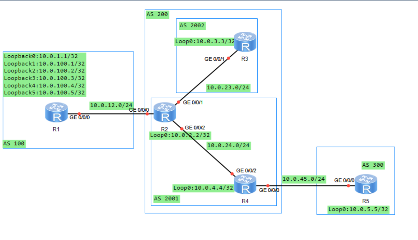
11.2.4 实验编址表
| 设备 | 接口 | IP地址 | 子网掩码 | 默认网关 |
|---|---|---|---|---|
| R1(AR2220) | GE0/0/0 | 10.0.12.1 | 255.255.255.0 | N/A |
| R1(AR2220) | LoopBack 0 | 10.0.1.1 | 255.255.255.255 | N/A |
| R1(AR2220) | LoopBack 1 | 10.0.100.1 | 255.255.255.255 | N/A |
| R1(AR2220) | LoopBack 2 | 10.0.100.2 | 255.255.255.255 | N/A |
| R1(AR2220) | LoopBack 3 | 10.0.100.3 | 255.255.255.255 | N/A |
| R1(AR2220) | LoopBack 4 | 10.0.100.4 | 255.255.255.255 | N/A |
| R1(AR2220) | LoopBack 5 | 10.0.100.5 | 255.255.255.255 | N/A |
| R2(AR2220) | GE0/0/0 | 10.0.12.2 | 255.255.255.0 | N/A |
| R2(AR2220) | GE0/0/1 | 10.0.23.2 | 255.255.255.0 | N/A |
| R2(AR2220) | GE0/0/2 | 10.0.24.2 | 255.255.255.0 | N/A |
| R2(AR2220) | LoopBack 0 | 10.0.2.2 | 255.255.255.255 | N/A |
| R3(AR2220) | GE0/0/0 | 10.0.23.3 | 255.255.255.0 | N/A |
| R3(AR2220) | LoopBack 0 | 10.0.3.3 | 255.255.255.255 | N/A |
| R4(AR2220) | GE0/0/0 | 10.0.45.4 | 255.255.255.0 | N/A |
| R4(AR2220) | GE0/0/2 | 10.0.24.4 | 255.255.255.0 | N/A |
| R4(AR2220) | LoopBack 0 | 10.0.4.4 | 255.255.255.255 | N/A |
| R5(AR2220) | GE0/0/0 | 10.0.45.5 | 255.255.255.0 | N/A |
| R5(AR2220) | LoopBack 0 | 10.0.5.5 | 255.255.255.255 | N/A |
| ### 11.2.5 实验步骤 | ||||
| #### 11.2.5.1 基本配置 | ||||
| 根据实验编制表进行基本配置,并使用ping命令检测R1和R2之间的连通性。 | ||||
| #### 11.2.5.2 配置BGP路由协议 | ||||
| 1、在AS 200内进行OSPF协议的配置 |
[R2]ospf 1 router-id 10.0.2.2
[R2-ospf-1]area 0
[R2-ospf-1-area-0.0.0.0]network 10.0.23.0 0.0.0.255
[R2-ospf-1-area-0.0.0.0]network 10.0.24.0 0.0.0.255
[R2-ospf-1-area-0.0.0.0]network 10.0.2.2 0.0.0.0

[R3]ospf 1 router-id 10.0.3.3
[R3-ospf-1]area 0
[R3-ospf-1-area-0.0.0.0]network 10.0.3.3 0.0.0.0
[R3-ospf-1-area-0.0.0.0]network 10.0.23.0 0.0.0.255

[R4]ospf 1 router-id 10.0.4.4
[R4-ospf-1]area 0
[R4-ospf-1-area-0.0.0.0]network 10.0.4.4 0.0.0.0
[R4-ospf-1-area-0.0.0.0]network 10.0.24.0 0.0.0.255
2、配置完成后,在R2上查看OSPF邻居关系。观察到,R2与R3和R4的OSPF邻居状态均为Full.
[R2]dis ospf peer brief

     OSPF Process 1 with Router ID 10.0.2.2
          Peer Statistic Information
 ----------------------------------------------------------------------------
 Area Id          Interface                        Neighbor id      State
 0.0.0.0          GigabitEthernet0/0/1             10.0.3.3         Full
 0.0.0.0          GigabitEthernet0/0/2             10.0.4.4         Full
 ----------------------------------------------------------------------------
3、配置BGP协议,其中R1属于AS 100,R2和R4属于联盟AS 200的成员AS 2001,R3属于联盟AS 200的成员AS 2002,R5属于AS 300。
[R1]bgp 100
[R1-bgp]router-id 10.0.1.1
[R1-bgp]peer 10.0.12.2 as 200
[R1-bgp]network 10.0.100.1 32
[R1-bgp]network 10.0.100.2 32
[R1-bgp]network 10.0.100.3 32
[R1-bgp]network 10.0.100.4 32
[R1-bgp]network 10.0.100.5 32

[R2]bgp 2001
[R2-bgp]router-id 10.0.2.2
[R2-bgp]confederation id 200
[R2-bgp]confederation peer-as 2002
[R2-bgp]peer 10.0.23.3 as 2002
[R2-bgp]peer 10.0.23.3 next-hop-local
[R2-bgp]peer 10.0.24.4 as 2001
[R2-bgp]peer 10.0.24.4 next-hop-local
[R2-bgp]peer 10.0.12.1 as 100

[R3]bgp 2002
[R3-bgp]router-id 10.0.3.3
[R3-bgp]confederation id 200
[R3-bgp]confederation peer-as 2001
[R3-bgp]peer 10.0.23.2 as 2001

[R4]bgp 2001
[R4-bgp]router-id 10.0.4.4
[R4-bgp]confederation id 200
[R4-bgp]peer 10.0.24.2 as 2001
[R4-bgp]peer 10.0.24.2 next-hop-local
[R4-bgp]peer 10.0.45.5 as 300

[R5]bgp 300
[R5-bgp]router-id 10.0.5.5
[R5-bgp]peer 10.0.45.4 as 200
4、配置完成后,在R2上查看BGP邻居信息。观察到,R2与R1、R3、R4都已成功建立BGP邻居。
[R2]dis bgp peer

 BGP local router ID : 10.0.2.2
 Local AS number : 2001
 Total number of peers : 3        Peers in established state : 3

  Peer            V          AS  MsgRcvd  MsgSent  OutQ  Up/Down       State Pre
fRcv

  10.0.12.1       4         100        8        7     0 00:05:50 Established
   5
  10.0.23.3       4        2002        5        7     0 00:03:44 Established
   0
  10.0.24.4       4        2001        3        5     0 00:01:55 Established
   0
5、在R5上查看BGP路由表。观察到,R5已经接收到R1通告的所有路由信息。
[R5]dis bgp routing-table

 BGP Local router ID is 10.0.5.5
 Status codes: * - valid, > - best, d - damped,
               h - history,  i - internal, s - suppressed, S - Stale
               Origin : i - IGP, e - EGP, ? - incomplete

 Total Number of Routes: 5
      Network            NextHop        MED        LocPrf    PrefVal Path/Ogn

 *>   10.0.100.1/32      10.0.45.4                             0      200 100i
 *>   10.0.100.2/32      10.0.45.4                             0      200 100i
 *>   10.0.100.3/32      10.0.45.4                             0      200 100i
 *>   10.0.100.4/32      10.0.45.4                             0      200 100i
 *>   10.0.100.5/32      10.0.45.4                             0      200 100i
11.2.5.3 使用No_Export团体属性控制路由信息传递
1、现要求10.0.100.2/32这条路由信息只能被联盟AS 200中的路由器接收到,而不能被AS 300中的路由器接收到。使用团体属性No_Export满足要求。在R1上使用前缀列表方法来匹配路由10.0.100.2/32.
[R1]ip ip-prefix 1 permit 10.0.100.2 32
2、在R1上创建Router-Policy,并在R1上调用Route-Policy
[R1]route-policy 1 permit node 10
Info: New Sequence of this List.
[R1-route-policy]if-match ip-prefix 1
[R1-route-policy]apply community no-export
[R1-route-policy]qu
[R1]route-policy 1 permit node 20
Info: New Sequence of this List.
[R1-route-policy]bgp 100
[R1-bgp]peer 10.0.12.2 route-policy 1 export
3、在R5上查看BGP路由表。观察到R5仍然接收到了10.0.100.2/32这条路由信息。这是因为在缺省情况下,路由器向BGP对等体传递路由信息时不会携带团体属性。
[R5]dis bgp routing-table

 BGP Local router ID is 10.0.5.5
 Status codes: * - valid, > - best, d - damped,
               h - history,  i - internal, s - suppressed, S - Stale
               Origin : i - IGP, e - EGP, ? - incomplete

 Total Number of Routes: 5
      Network            NextHop        MED        LocPrf    PrefVal Path/Ogn

 *>   10.0.100.1/32      10.0.45.4                             0      200 100i
 *>   10.0.100.2/32      10.0.45.4                             0      200 100i
 *>   10.0.100.3/32      10.0.45.4                             0      200 100i
 *>   10.0.100.4/32      10.0.45.4                             0      200 100i
 *>   10.0.100.5/32      10.0.45.4                             0      200 100i
4、在R1上执行peer 10.0.12.2 advertise-community命令向R2传递BGP路由信息时携带团体属性。
[R1-bgp]peer 10.0.12.2 advertise-community
5、同样在R2、R4上也做相同配置,保证R2向R3和R4传递BGP路由信息时携带团体属性,并且R4在向R5传递BGP路由信息时也携带团体属性。
[R2]bgp 2001
[R2-bgp]peer 10.0.23.3 advertise-community
[R2-bgp]peer 10.0.24.4 advertise-community

[R4]bgp 2001
[R4-bgp]peer 10.0.45.5 advertise-community
6、配置完成后,在R5上查看BGP路由表。观察10.0.100.2/32这条路由信息已经消失。
[R5]dis bgp routing-table

 BGP Local router ID is 10.0.5.5
 Status codes: * - valid, > - best, d - damped,
               h - history,  i - internal, s - suppressed, S - Stale
               Origin : i - IGP, e - EGP, ? - incomplete

 Total Number of Routes: 4
      Network            NextHop        MED        LocPrf    PrefVal Path/Ogn

 *>   10.0.100.1/32      10.0.45.4                             0      200 100i
 *>   10.0.100.3/32      10.0.45.4                             0      200 100i
 *>   10.0.100.4/32      10.0.45.4                             0      200 100i
 *>   10.0.100.5/32      10.0.45.4                             0      200 100i
7、在R2、R3、R4上查看携带团体属性的BGP路由表。观察到,R2、R3、R4的10.0.100.2/32这条路由都携带了No-Export团体属性。此时,该BGP路由不会传递给EBGP邻居,但在联盟内部的EBGP邻居之间是可以传递的。
[R2]dis bgp routing-table community

 BGP Local router ID is 10.0.2.2
 Status codes: * - valid, > - best, d - damped,
               h - history,  i - internal, s - suppressed, S - Stale
               Origin : i - IGP, e - EGP, ? - incomplete

 Total Number of Routes: 1
      Network            NextHop        MED        LocPrf    PrefVal Community

 *>   10.0.100.2/32      10.0.12.1       0                     0      no-export

<R3>dis bgp routing-table community

 BGP Local router ID is 10.0.3.3
 Status codes: * - valid, > - best, d - damped,
               h - history,  i - internal, s - suppressed, S - Stale
               Origin : i - IGP, e - EGP, ? - incomplete

 Total Number of Routes: 1
      Network            NextHop        MED        LocPrf    PrefVal Community

 *>i  10.0.100.2/32      10.0.23.2       0          100        0      no-export

<R4>dis bgp routing-table community

 BGP Local router ID is 10.0.4.4
 Status codes: * - valid, > - best, d - damped,
               h - history,  i - internal, s - suppressed, S - Stale
               Origin : i - IGP, e - EGP, ? - incomplete

 Total Number of Routes: 1
      Network            NextHop        MED        LocPrf    PrefVal Community

 *>i  10.0.100.2/32      10.0.24.2       0          100        0      no-export
11.2.5.4 使用No-Export-Subconfed团体属性控制路由信息传递
1、现要求10.0.100.3/32这条路由只能够被联盟AS 200成员AS 2001中的路由器收到,而不能被成员AS 2002以及AS 300中的路由器收到。在R1上使用前缀列表方法来匹配路由10.0.100.3/32
[R1]ip ip-prefix 2 permit 10.0.100.3 32
2、在R1上创建新的路由策略的Node。
[R1]route-policy 1 permit node 15
Info: New Sequence of this List.
[R1-route-policy]if-match ip-prefix 2
[R1-route-policy]apply community no-export-subconfed
3、配置完成后,在R2、R3、R4、R5上查看BGP路由表。观察到,R2、R4接收到了10.0.100.3/这条路由信息。R3、R5未接收到了10.0.100.3/这条路由信息
<R2>dis bgp routing-table

 BGP Local router ID is 10.0.2.2
 Status codes: * - valid, > - best, d - damped,
               h - history,  i - internal, s - suppressed, S - Stale
               Origin : i - IGP, e - EGP, ? - incomplete

 Total Number of Routes: 5
      Network            NextHop        MED        LocPrf    PrefVal Path/Ogn

 *>   10.0.100.1/32      10.0.12.1       0                     0      100i
 *>   10.0.100.2/32      10.0.12.1       0                     0      100i
 *>   10.0.100.3/32      10.0.12.1       0                     0      100i
 *>   10.0.100.4/32      10.0.12.1       0                     0      100i
 *>   10.0.100.5/32      10.0.12.1       0                     0      100i

<R3>dis bgp routing-table

 BGP Local router ID is 10.0.3.3
 Status codes: * - valid, > - best, d - damped,
               h - history,  i - internal, s - suppressed, S - Stale
               Origin : i - IGP, e - EGP, ? - incomplete

 Total Number of Routes: 4
      Network            NextHop        MED        LocPrf    PrefVal Path/Ogn

 *>i  10.0.100.1/32      10.0.23.2       0          100        0      (2001) 100
i
 *>i  10.0.100.2/32      10.0.23.2       0          100        0      (2001) 100
i
 *>i  10.0.100.4/32      10.0.23.2       0          100        0      (2001) 100
i
 *>i  10.0.100.5/32      10.0.23.2       0          100        0      (2001) 100
i

<R4>dis bgp routing-table

 BGP Local router ID is 10.0.4.4
 Status codes: * - valid, > - best, d - damped,
               h - history,  i - internal, s - suppressed, S - Stale
               Origin : i - IGP, e - EGP, ? - incomplete

 Total Number of Routes: 5
      Network            NextHop        MED        LocPrf    PrefVal Path/Ogn

 *>i  10.0.100.1/32      10.0.24.2       0          100        0      100i
 *>i  10.0.100.2/32      10.0.24.2       0          100        0      100i
 *>i  10.0.100.3/32      10.0.24.2       0          100        0      100i
 *>i  10.0.100.4/32      10.0.24.2       0          100        0      100i
 *>i  10.0.100.5/32      10.0.24.2       0          100        0      100i

<R5>dis bgp routing-table

 BGP Local router ID is 10.0.5.5
 Status codes: * - valid, > - best, d - damped,
               h - history,  i - internal, s - suppressed, S - Stale
               Origin : i - IGP, e - EGP, ? - incomplete

 Total Number of Routes: 3
      Network            NextHop        MED        LocPrf    PrefVal Path/Ogn

 *>   10.0.100.1/32      10.0.45.4                             0      200 100i
 *>   10.0.100.4/32      10.0.45.4                             0      200 100i
 *>   10.0.100.5/32      10.0.45.4                             0      200 100i
4、在R2和R4上查看携带团体属性的BGP路由表。观察到R2、R4上10.0.100.3/32这条路由信息都携带了no-export-subconfed团体属性。说明,这种属性的BGP路由可以在联盟中的成员AS内部传递,但不会在成员AS 之间传递,也不会在EBGP邻居之间传递。
<R2>dis bgp routing-table community

 BGP Local router ID is 10.0.2.2
 Status codes: * - valid, > - best, d - damped,
               h - history,  i - internal, s - suppressed, S - Stale
               Origin : i - IGP, e - EGP, ? - incomplete

 Total Number of Routes: 2
      Network            NextHop        MED        LocPrf    PrefVal Community

 *>   10.0.100.2/32      10.0.12.1       0                     0      no-export
 *>   10.0.100.3/32      10.0.12.1       0                     0      no-export-
subconfed

<R4>dis bgp routing-table community

 BGP Local router ID is 10.0.4.4
 Status codes: * - valid, > - best, d - damped,
               h - history,  i - internal, s - suppressed, S - Stale
               Origin : i - IGP, e - EGP, ? - incomplete

 Total Number of Routes: 2
      Network            NextHop        MED        LocPrf    PrefVal Community

 *>i  10.0.100.2/32      10.0.24.2       0          100        0      no-export
 *>i  10.0.100.3/32      10.0.24.2       0          100        0      no-export-
subconfed
11.2.5.5 使用No-Advertise团体属性控制路由信息传递
1、现要求10.0.100.4/32这条路由只能够被R2收到,而不能被其他路由器收到。在R1上使用前缀列表方法来匹配路由10.0.100.4/32
[R1]ip ip-prefix 3 permit 10.0.100.4 32
2、在R1上创建新的路由策略的Node。
[R1]route-policy 1 permit node 18
Info: New Sequence of this List.
[R1-route-policy]if-match ip-prefix 3
[R1-route-policy]apply community no-advertise
3、配置完成后,在R2、R3、R4和R5上查看BGP路由表。观察到,只有R2接收到了10.0.100.4/32这条路由。
<R2>dis bgp routing-table

 BGP Local router ID is 10.0.2.2
 Status codes: * - valid, > - best, d - damped,
               h - history,  i - internal, s - suppressed, S - Stale
               Origin : i - IGP, e - EGP, ? - incomplete

 Total Number of Routes: 5
      Network            NextHop        MED        LocPrf    PrefVal Path/Ogn

 *>   10.0.100.1/32      10.0.12.1       0                     0      100i
 *>   10.0.100.2/32      10.0.12.1       0                     0      100i
 *>   10.0.100.3/32      10.0.12.1       0                     0      100i
 *>   10.0.100.4/32      10.0.12.1       0                     0      100i
 *>   10.0.100.5/32      10.0.12.1       0                     0      100i

<R3>dis bgp routing-table

 BGP Local router ID is 10.0.3.3
 Status codes: * - valid, > - best, d - damped,
               h - history,  i - internal, s - suppressed, S - Stale
               Origin : i - IGP, e - EGP, ? - incomplete

 Total Number of Routes: 3
      Network            NextHop        MED        LocPrf    PrefVal Path/Ogn

 *>i  10.0.100.1/32      10.0.23.2       0          100        0      (2001) 100
i
 *>i  10.0.100.2/32      10.0.23.2       0          100        0      (2001) 100
i
 *>i  10.0.100.5/32      10.0.23.2       0          100        0      (2001) 100
i

<R4>dis bgp routing-table

 BGP Local router ID is 10.0.4.4
 Status codes: * - valid, > - best, d - damped,
               h - history,  i - internal, s - suppressed, S - Stale
               Origin : i - IGP, e - EGP, ? - incomplete

 Total Number of Routes: 4
      Network            NextHop        MED        LocPrf    PrefVal Path/Ogn

 *>i  10.0.100.1/32      10.0.24.2       0          100        0      100i
 *>i  10.0.100.2/32      10.0.24.2       0          100        0      100i
 *>i  10.0.100.3/32      10.0.24.2       0          100        0      100i
 *>i  10.0.100.5/32      10.0.24.2       0          100        0      100i

<R5>dis bgp routing-table

 BGP Local router ID is 10.0.5.5
 Status codes: * - valid, > - best, d - damped,
               h - history,  i - internal, s - suppressed, S - Stale
               Origin : i - IGP, e - EGP, ? - incomplete

 Total Number of Routes: 2
      Network            NextHop        MED        LocPrf    PrefVal Path/Ogn

 *>   10.0.100.1/32      10.0.45.4                             0      200 100i
 *>   10.0.100.5/32      10.0.45.4                             0      200 100i
4、在R2上查看携带团体属性的BGP路由表。观察到,10.0.100.4/32这条路由携带了no-advertise团体属性,因此此路由不会被R2传递给BGP邻居。
<R2>dis bgp routing-table community

 BGP Local router ID is 10.0.2.2
 Status codes: * - valid, > - best, d - damped,
               h - history,  i - internal, s - suppressed, S - Stale
               Origin : i - IGP, e - EGP, ? - incomplete

 Total Number of Routes: 3
      Network            NextHop        MED        LocPrf    PrefVal Community

 *>   10.0.100.2/32      10.0.12.1       0                     0      no-export
 *>   10.0.100.3/32      10.0.12.1       0                     0      no-export-
subconfed
 *>   10.0.100.4/32      10.0.12.1       0                     0      no-adverti
se
11.2.5.6 使用自定义团体属性控制路由信息传递
1、现要求10.0.100.5/32这条路由只能够被R2和R3收到,而不能被R4和R5收到。在R1上使用前缀列表方法来匹配路由10.0.100.5/32
[R1]ip ip-prefix 4 permit 10.0.100.5 32
2、在R1上创建新的路由策略的Node。
[R1]route-policy 1 permit node 19
[R1-route-policy]if-match ip-prefix 4
[R1-route-policy]apply community 100:1
3、配置完成后,查看R2、R3、R4和R5上查看BGP路由表。观察到,R2、R3、R4和R5都接收到了10.0.100.5/32这条路由。这是因为自定义团体属性在缺省情况下,没有相应的动作,仅仅是为路由信息添加标识。
<R2>dis bgp routing-table

 BGP Local router ID is 10.0.2.2
 Status codes: * - valid, > - best, d - damped,
               h - history,  i - internal, s - suppressed, S - Stale
               Origin : i - IGP, e - EGP, ? - incomplete

 Total Number of Routes: 5
      Network            NextHop        MED        LocPrf    PrefVal Path/Ogn

 *>   10.0.100.1/32      10.0.12.1       0                     0      100i
 *>   10.0.100.2/32      10.0.12.1       0                     0      100i
 *>   10.0.100.3/32      10.0.12.1       0                     0      100i
 *>   10.0.100.4/32      10.0.12.1       0                     0      100i
 *>   10.0.100.5/32      10.0.12.1       0                     0      100i

<R3>dis bgp routing-table

 BGP Local router ID is 10.0.3.3
 Status codes: * - valid, > - best, d - damped,
               h - history,  i - internal, s - suppressed, S - Stale
               Origin : i - IGP, e - EGP, ? - incomplete

 Total Number of Routes: 3
      Network            NextHop        MED        LocPrf    PrefVal Path/Ogn

 *>i  10.0.100.1/32      10.0.23.2       0          100        0      (2001) 100
i
 *>i  10.0.100.2/32      10.0.23.2       0          100        0      (2001) 100
i
 *>i  10.0.100.5/32      10.0.23.2       0          100        0      (2001) 100
i

<R4>dis bgp routing-table

 BGP Local router ID is 10.0.4.4
 Status codes: * - valid, > - best, d - damped,
               h - history,  i - internal, s - suppressed, S - Stale
               Origin : i - IGP, e - EGP, ? - incomplete

 Total Number of Routes: 4
      Network            NextHop        MED        LocPrf    PrefVal Path/Ogn

 *>i  10.0.100.1/32      10.0.24.2       0          100        0      100i
 *>i  10.0.100.2/32      10.0.24.2       0          100        0      100i
 *>i  10.0.100.3/32      10.0.24.2       0          100        0      100i
 *>i  10.0.100.5/32      10.0.24.2       0          100        0      100i

<R5>dis bgp routing-table

 BGP Local router ID is 10.0.5.5
 Status codes: * - valid, > - best, d - damped,
               h - history,  i - internal, s - suppressed, S - Stale
               Origin : i - IGP, e - EGP, ? - incomplete

 Total Number of Routes: 2
      Network            NextHop        MED        LocPrf    PrefVal Path/Ogn

 *>   10.0.100.1/32      10.0.45.4                             0      200 100i
 *>   10.0.100.5/32      10.0.45.4                             0      200 100i
4、在R4上匹配自定义团体属性为100:1的路由
[R4]ip community-filter 1 permit 100:1
5、在R4上创建route-policy,并在接收R2传递过来的路由时调用route-policy
[R4]route-policy 1 deny node 10
Info: New Sequence of this List.
[R4-route-policy]if-match community-filter 1
[R4-route-policy]qu
[R4]route-policy 1 permit node 20
Info: New Sequence of this List.

[R4-route-policy]bgp 2001
[R4-bgp]peer  10.0.24.2 route-policy 1 import
6、配置完成后,在R2、R3、R4、R5上查看BGP路由表。10.0.100.5/32这条路由只能够被R2和R3收到,而不能被R4和R5收到。
<R2>dis bgp routing-table

 BGP Local router ID is 10.0.2.2
 Status codes: * - valid, > - best, d - damped,
               h - history,  i - internal, s - suppressed, S - Stale
               Origin : i - IGP, e - EGP, ? - incomplete

 Total Number of Routes: 5
      Network            NextHop        MED        LocPrf    PrefVal Path/Ogn

 *>   10.0.100.1/32      10.0.12.1       0                     0      100i
 *>   10.0.100.2/32      10.0.12.1       0                     0      100i
 *>   10.0.100.3/32      10.0.12.1       0                     0      100i
 *>   10.0.100.4/32      10.0.12.1       0                     0      100i
 *>   10.0.100.5/32      10.0.12.1       0                     0      100i

<R3>dis bgp routing-table

 BGP Local router ID is 10.0.3.3
 Status codes: * - valid, > - best, d - damped,
               h - history,  i - internal, s - suppressed, S - Stale
               Origin : i - IGP, e - EGP, ? - incomplete

 Total Number of Routes: 3
      Network            NextHop        MED        LocPrf    PrefVal Path/Ogn

 *>i  10.0.100.1/32      10.0.23.2       0          100        0      (2001) 100
i
 *>i  10.0.100.2/32      10.0.23.2       0          100        0      (2001) 100
i
 *>i  10.0.100.5/32      10.0.23.2       0          100        0      (2001) 100
i

[R4]dis bgp routing-table

 BGP Local router ID is 10.0.4.4
 Status codes: * - valid, > - best, d - damped,
               h - history,  i - internal, s - suppressed, S - Stale
               Origin : i - IGP, e - EGP, ? - incomplete

 Total Number of Routes: 3
      Network            NextHop        MED        LocPrf    PrefVal Path/Ogn

 *>i  10.0.100.1/32      10.0.24.2       0          100        0      100i
 *>i  10.0.100.2/32      10.0.24.2       0          100        0      100i
 *>i  10.0.100.3/32      10.0.24.2       0          100        0      100i

<R5>dis bgp routing-table

 BGP Local router ID is 10.0.5.5
 Status codes: * - valid, > - best, d - damped,
               h - history,  i - internal, s - suppressed, S - Stale
               Origin : i - IGP, e - EGP, ? - incomplete

 Total Number of Routes: 1
      Network            NextHop        MED        LocPrf    PrefVal Path/Ogn

 *>   10.0.100.1/32      10.0.45.4                             0      200 100i
<R5>
7、在R2和R3上查看携带团体属性的BGP路由表。观察到R2和R3上10.0.100.5/32这条路由携带了自定义的团体属性100:1.
<R2>dis bgp routing-table community

 BGP Local router ID is 10.0.2.2
 Status codes: * - valid, > - best, d - damped,
               h - history,  i - internal, s - suppressed, S - Stale
               Origin : i - IGP, e - EGP, ? - incomplete

 Total Number of Routes: 4
      Network            NextHop        MED        LocPrf    PrefVal Community

 *>   10.0.100.2/32      10.0.12.1       0                     0      no-export
 *>   10.0.100.3/32      10.0.12.1       0                     0      no-export-
subconfed
 *>   10.0.100.4/32      10.0.12.1       0                     0      no-adverti
se
 *>   10.0.100.5/32      10.0.12.1       0                     0      <100:1>

<R3>dis bgp routing-table community

 BGP Local router ID is 10.0.3.3
 Status codes: * - valid, > - best, d - damped,
               h - history,  i - internal, s - suppressed, S - Stale
               Origin : i - IGP, e - EGP, ? - incomplete

 Total Number of Routes: 2
      Network            NextHop        MED        LocPrf    PrefVal Community

 *>i  10.0.100.2/32      10.0.23.2       0          100        0      no-export
 *>i  10.0.100.5/32      10.0.23.2       0          100        0      <100:1>
11.3 思考
带有No-Advertise团体属性的路由可以被传递给联盟EBGP对等体吗? 答:不会,因为路由器接收到一条携带No-Advertise团体属性的路由后,不会将它发布给任何BGP对等体。
十二、BGP路由反射器
12.1 原理概述
缺省情况下,路由器从它的一个IBGP对等体那里接收到的路由条目不会被该路由器再传递给其他IBGP对等体,这个原则称为BGP水平分割原则,该原则的根本作用时防止AS内部的BGP路由环路。因此,在AS内部,一般需要每台路由器都运行BGP协议并建立全互联的IBGP对等体关系,这样才能避免BGP路由黑洞等问题。对于有n个BGP路由器的AS来说,全互联的IBGP对等体关系将有nX(n-1)/2个。
路由反射器的使用,可以在很大程度上减少大型AS中IBGP对等体关系的数量并简化相应的配置和维护工作。BGP路由反射器是AS内部IBGP对等体关系的数量并简化相应的配置和维护工作。BGP路由反射器是AS内部IBGP网络环境中的一种特殊角色,其他的角色还有反射器的客户端和非客户端。一个反射器和它的所有客户端一起被统称为一个Cluster;客户端与它的反射器建立的是IBGP对等体关系;客户端之间无需建立IBGP对等体关系;非客户端和反射器建立的是IBGP对等体关系;非客户端和客户端之间无需建立IBGP对等体关系;一个AS内部可以有多个Cluster;一个Cluster中可以有多台反射器。另外,EBGP对等体之间是不存在BGP路由反射器这个概念的。
BGP路由反射器在反射路由的时候遵循的原则是:从一个非客户端那里接收到的路由,反射器会将它只传递给所有的客户端;从一个客户端那里接收到的路由。反射器会将它传递给所有其他的客户端以及所有的非客户端;从EBGP对等体那里接收到的路由,反射器会将它传递给所有的客户端和非客户端。
12.2 BGP路由反射器配置实验
12.2.1 实验目的
1、理解BGP路由反射器的应用场景 2、理解BGP路由反射器的工作原理 3、掌握BGP路由反射器的基本配置方法
12.2.2 实验内容
本实验包含了两个AS,两个cluster。R1、R2、R3属于cluster1,R4、R5、R6属于cluster2,R7不属于任何cluster。在AS 100内部,所有路由器都运行OSPF作为IGP,并将各自的LoopBack 0接口宣告进OSPF进程中,使得各路由器可以使用LoopBack0接口来建立全互联的IBGP对等体关系。为减少配置工作量,使用路由反射器,要求是:在cluster1中,R1为路由反射器,R2和R3为其客户端;在cluster2中,R4为路由反射器,R5、R6为其客户端;R7为非客户端;R1与R8为EBGP对等体关系。
12.2.3 实验拓扑

12.2.4 实验编址表
| 设备 | 接口 | IP地址 | 子网掩码 | 默认网关 |
|---|---|---|---|---|
| R1(AR2220) | GE0/0/0 | 10.0.14.1 | 255.255.255.0 | N/A |
| R1(AR2220) | GE0/0/1 | 10.0.12.1 | 255.255.255.0 | N/A |
| R1(AR2220) | GE0/0/2 | 10.0.13.1 | 255.255.255.0 | N/A |
| R1(AR2220) | GE1/0/0 | 10.0.18.1 | 255.255.255.0 | N/A |
| R1(AR2220) | LoopBack 0 | 10.0.1.1 | 255.255.255.255 | N/A |
| R2(AR2220) | GE0/0/1 | 10.0.12.2 | 255.255.255.0 | N/A |
| R2(AR2220) | LoopBack 0 | 10.0.2.2 | 255.255.255.255 | N/A |
| R2(AR2220) | LoopBack 1 | 10.0.22.22 | 255.255.255.255 | N/A |
| R3(AR2220) | GE0/0/2 | 10.0.13.3 | 255.255.255.0 | N/A |
| R3(AR2220) | LoopBack 0 | 10.0.3.3 | 255.255.255.255 | N/A |
| R4(AR2220) | GE0/0/0 | 10.0.14.4 | 255.255.255.0 | N/A |
| R4(AR2220) | GE0/0/1 | 10.0.45.4 | 255.255.255.0 | N/A |
| R4(AR2220) | GE0/0/2 | 10.0.46.4 | 255.255.255.0 | N/A |
| R4(AR2220) | GE1/0/0 | 10.0.47.4 | 255.255.255.0 | N/A |
| R4(AR2220) | LoopBack 0 | 10.0.4.4 | 255.255.255.255 | N/A |
| R5(AR2220) | GE0/0/1 | 10.0.45.5 | 255.255.255.0 | N/A |
| R5(AR2220) | LoopBack 0 | 10.0.5.5 | 255.255.255.255 | N/A |
| R6(AR2220) | GE0/0/2 | 10.0.46.6 | 255.255.255.0 | N/A |
| R6(AR2220) | LoopBack 0 | 10.0.6.6 | 255.255.255.255 | N/A |
| R7(AR2220) | GE0/0/0 | 10.0.47.7 | 255.255.255.0 | N/A |
| R7(AR2220) | LoopBack 0 | 10.0.7.7 | 255.255.255.255 | N/A |
| R8(AR2220) | GE0/0/0 | 10.0.18.8 | 255.255.255.0 | N/A |
| R8(AR2220) | LoopBack 0 | 10.0.8.8 | 255.255.255.255 | N/A |
| ### 12.2.5 实验步骤 | ||||
| #### 12.2.5.1 基本配置 | ||||
| 根据实验编制表进行基本配置,并使用ping命令检测R1和R2之间的连通性。 | ||||
| #### 12.2.5.2 配置OSPF协议 | ||||
| 1、AS 100内部的路由器之间都能够使用LoopBack 0接口建立IBGP对等体关系,需要在每台路由器上配置OSPF路由协议,并将LoopBack 0接口通告进OSPF进程。 |
[R1]ospf 1 router-id 10.0.1.1
[R1-ospf-1]area 0
[R1-ospf-1-area-0.0.0.0]network 10.0.1.1 0.0.0.0
[R1-ospf-1-area-0.0.0.0]network 10.0.13.0 0.0.0.255
[R1-ospf-1-area-0.0.0.0]network 10.0.14.0 0.0.0.255
[R1-ospf-1-area-0.0.0.0]network 10.0.12.0 0.0.0.255

[R2]ospf 1 router-id 10.0.2.2
[R2-ospf-1]area 0
[R2-ospf-1-area-0.0.0.0]network 10.0.2.2 0.0.0.0
[R2-ospf-1-area-0.0.0.0]network 10.0.12.0 0.0.0.255

[R3]ospf 1 router-id 10.0.3.3
[R3-ospf-1]area 0
[R3-ospf-1-area-0.0.0.0]network 10.0.3.3 0.0.0.0
[R3-ospf-1-area-0.0.0.0]network 10.0.13.0 0.0.0.255

[R4]ospf 1 router-id 10.0.4.4
[R4-ospf-1]area 0
[R4-ospf-1-area-0.0.0.0]network 10.0.4.4 0.0.0.0
[R4-ospf-1-area-0.0.0.0]network 10.0.14.0 0.0.0.255
[R4-ospf-1-area-0.0.0.0]network 10.0.45.0 0.0.0.255
[R4-ospf-1-area-0.0.0.0]network 10.0.46.0 0.0.0.255
[R4-ospf-1-area-0.0.0.0]network 10.0.47.0 0.0.0.255

[R5]ospf 1 router-id 10.0.5.5
[R5-ospf-1]area 0
[R5-ospf-1-area-0.0.0.0]network 10.0.5.5 0.0.0.0
[R5-ospf-1-area-0.0.0.0]network 10.0.45.0 0.0.0.255

[R6]ospf 1 router-id 10.0.6.6
[R6-ospf-1]area 0
[R6-ospf-1-area-0.0.0.0]network 10.0.6.6 0.0.0.0
[R6-ospf-1-area-0.0.0.0]network 10.0.46.0 0.0.0.255

[R7]ospf 1 router-id 10.0.7.7
[R7-ospf-1]area 0
[R7-ospf-1-area-0.0.0.0]network 10.0.7.7 0.0.0.0
[R7-ospf-1-area-0.0.0.0]network 10.0.47.0 0.0.0.255
12.2.5.3 配置BGP路由协议
1、配置BGP路由协议,在AS 100内部的每台路由器上使用LoopBack0接口建立全互联的IBGP对等体关系,并通告各自的LoopBack接口到BGP进程中。
[R1]bgp 100
[R1-bgp]router-id 10.0.1.1
[R1-bgp]peer 10.0.2.2 as 100
[R1-bgp]peer 10.0.2.2 connect-interface loop 0
[R1-bgp]peer 10.0.2.2 next-hop-local
[R1-bgp]peer 10.0.3.3 as 100
[R1-bgp]peer 10.0.3.3 connect-interface loop 0
[R1-bgp]peer 10.0.3.3 next-hop-local
[R1-bgp]peer 10.0.4.4 as 100
[R1-bgp]peer 10.0.4.4 connect-interface loop 0
[R1-bgp]peer 10.0.4.4 next-hop-local
[R1-bgp]peer 10.0.5.5 as 100
[R1-bgp]peer 10.0.5.5 next-hop-local
[R1-bgp]peer 10.0.5.5 connect-interface loop 0
[R1-bgp]peer 10.0.6.6 as 100
[R1-bgp]peer 10.0.6.6 connect-interface loop 0
[R1-bgp]peer 10.0.6.6 next-hop-local
[R1-bgp]peer 10.0.7.7 as 100
[R1-bgp]peer 10.0.7.7 connect-interface loop 0
[R1-bgp]peer 10.0.7.7 next-hop-local
[R1-bgp]network 10.0.1.1 32

[R2]bgp 100
[R2-bgp]router-id 10.0.2.2
[R2-bgp]peer 10.0.1.1 as 100
[R2-bgp]peer 10.0.1.1 connect-interface  loop 0
[R2-bgp]peer 10.0.3.3 as 100
[R2-bgp]peer 10.0.3.3 connect-interface loop 0
[R2-bgp]peer 10.0.4.4 as 100
[R2-bgp]peer 10.0.4.4 connect-interface loop 0
[R2-bgp]peer 10.0.5.5 as 100
[R2-bgp]peer 10.0.5.5 connect-interface loop 0
[R2-bgp]peer 10.0.6.6 as 100
[R2-bgp]peer 10.0.6.6 connect-interface loop 0
[R2-bgp]peer 10.0.7.7 as 100
[R2-bgp]peer 10.0.7.7 connect-interface loop 0
[R2-bgp]network 10.0.2.2 32

[R3]bgp 100
[R3-bgp]router-id 10.0.3.3
[R3-bgp]peer 10.0.1.1 as 100
[R3-bgp]peer 10.0.1.1 connect-interface loop 0
[R3-bgp]peer 10.0.2.2 as 100
[R3-bgp]peer 10.0.2.2 connect-interface loop 0
[R3-bgp]peer 10.0.4.4 as 100
[R3-bgp]peer 10.0.4.4 connect-interface loop 0
[R3-bgp]peer 10.0.5.5 as 100
[R3-bgp]peer 10.0.5.5 connect-interface loop 0
[R3-bgp]peer 10.0.6.6 as 100
[R3-bgp]peer 10.0.6.6 connect-interface loop 0
[R3-bgp]peer 10.0.7.7 as 100
[R3-bgp]peer 10.0.7.7 connect-interface loop 0
[R3-bgp]network 10.0.3.3 32

[R4]bgp 100
[R4-bgp]router-id 10.0.4.4
[R4-bgp]peer 10.0.1.1 as 100
[R4-bgp]peer 10.0.1.1 connect-interface  loop 0
[R4-bgp]peer 10.0.2.2 as 100
[R4-bgp]peer 10.0.2.2 connect-interface loop 0
[R4-bgp]peer 10.0.3.3 as 100
[R4-bgp]peer 10.0.3.3 connect-interface  loop 0
[R4-bgp]peer 10.0.5.5 as 100
[R4-bgp]peer 10.0.5.5 connect-interface  loop 0
[R4-bgp]peer 10.0.6.6 as 100
[R4-bgp]peer 10.0.6.6 connect-interface loo
[R4-bgp]peer 10.0.6.6 connect-interface loop 0
[R4-bgp]peer 10.0.7.7 as 100
[R4-bgp]peer 10.0.7.7 connect-interface  loop 0

[R5]bgp 100
[R5-bgp]router-id 10.0.5.5
[R5-bgp]peer 10.0.1.1 as 100
[R5-bgp]peer 10.0.1.1 connect-interface loop 0
[R5-bgp]peer 10.0.2.2 as 100
[R5-bgp]peer 10.0.2.2 connect-interface  loop 0
[R5-bgp]peer 10.0.3.3 as 100
[R5-bgp]peer 10.0.3.3 connect-interface loop 0
[R5-bgp]peer 10.0.4.4 as 100
[R5-bgp]peer 10.0.4.4 connect-interface loop 0
[R5-bgp]peer 10.0.6.6 as 100
[R5-bgp]peer 10.0.6.6 connect-interface loop 0
[R5-bgp]peer 10.0.7.7 as 100
[R5-bgp]peer 10.0.7.7 connect-interface loop 0
[R5-bgp]network 10.0.5.5 32

[R6]bgp 100
[R6-bgp]router-id 10.0.6.6
[R6-bgp]peer 10.0.1.1 as 100
[R6-bgp]peer 10.0.1.1 connect-interface loop 0
[R6-bgp]peer 10.0.2.2 as 100
[R6-bgp]peer 10.0.2.2 connect-interface  loop 0
[R6-bgp]peer 10.0.3.3 as 100
[R6-bgp]peer 10.0.3.3 connect-interface loop 0
[R6-bgp]peer 10.0.4.4 as 100
[R6-bgp]peer 10.0.4.4 connect-interface loop 0
[R6-bgp]peer 10.0.5.5 as 100
[R6-bgp]peer 10.0.5.5 connect-interface loop 0
[R6-bgp]peer 10.0.7.7 as 100
[R6-bgp]peer 10.0.7.7 connect-interface loop 0
[R6-bgp]network 10.0.6.6 32

[R7]bgp 100
[R7-bgp]router-id 10.0.7.7
[R7-bgp]peer 10.0.1.1 as 100
[R7-bgp]peer 10.0.1.1 connect-interface  loop 0
[R7-bgp]peer 10.0.2.2 as 100
[R7-bgp]peer 10.0.2.2 connect-interface loop 0
[R7-bgp]peer 10.0.3.3 as 100
[R7-bgp]peer 10.0.3.3 connect-interface loop 0
[R7-bgp]peer 10.0.4.4 as 100
[R7-bgp]peer 10.0.4.4 connect-interface loop 0
[R7-bgp]peer 10.0.4.4 connect-interface loop 0
[R7-bgp]peer 10.0.5.5 as 100
[R7-bgp]peer 10.0.5.5 connect-interface  loop 0
[R7-bgp]peer 10.0.6.6 as 100
[R7-bgp]peer 10.0.6.6 connect-interface loop 0
[R7-bgp]network 10.0.7.7 32
2、在R1和R8之间采用直连物理接口建立EBGP对等体关系,并通告R8的LoopBack0接口到BGP进程中。
[R1]bgp 100
[R1-bgp]peer 10.0.18.8 as 200

[R8]bgp 200
[R8-bgp]router-id 10.0.8.8
[R8-bgp]peer 10.0.18.1 as 100
[R8-bgp]network 10.0.8.8 32
3、配置完成后,查看R1-R8的BGP路由表。观察到,AS 100内部的路由器已经接收到了关于10.0.8.8/32的路由信息。R8只接收到了10.0.1.1/32的路由信息,没有接收到关于AS 100内部其他路由器的LoopBack0的路由信息。这是因为OSPF协议优先级高于BGP路由协议的优先级。
[R1]dis bgp routing-table

 BGP Local router ID is 10.0.1.1
 Status codes: * - valid, > - best, d - damped,
               h - history,  i - internal, s - suppressed, S - Stale
               Origin : i - IGP, e - EGP, ? - incomplete

 Total Number of Routes: 7
      Network            NextHop        MED        LocPrf    PrefVal Path/Ogn

 *>   10.0.1.1/32        0.0.0.0         0                     0      i
   i  10.0.2.2/32        10.0.2.2        0          100        0      i
   i  10.0.3.3/32        10.0.3.3        0          100        0      i
   i  10.0.5.5/32        10.0.5.5        0          100        0      i
   i  10.0.6.6/32        10.0.6.6        0          100        0      i
   i  10.0.7.7/32        10.0.7.7        0          100        0      i
 *>   10.0.8.8/32        10.0.18.8       0                     0      200i

<R2>dis bgp routing-table

 BGP Local router ID is 10.0.2.2
 Status codes: * - valid, > - best, d - damped,
               h - history,  i - internal, s - suppressed, S - Stale
               Origin : i - IGP, e - EGP, ? - incomplete

 Total Number of Routes: 7
      Network            NextHop        MED        LocPrf    PrefVal Path/Ogn

   i  10.0.1.1/32        10.0.1.1        0          100        0      i
 *>   10.0.2.2/32        0.0.0.0         0                     0      i
   i  10.0.3.3/32        10.0.3.3        0          100        0      i
   i  10.0.5.5/32        10.0.5.5        0          100        0      i
   i  10.0.6.6/32        10.0.6.6        0          100        0      i
   i  10.0.7.7/32        10.0.7.7        0          100        0      i
 *>i  10.0.8.8/32        10.0.1.1        0          100        0      200i

<R3>dis bgp routing-table

 BGP Local router ID is 10.0.3.3
 Status codes: * - valid, > - best, d - damped,
               h - history,  i - internal, s - suppressed, S - Stale
               Origin : i - IGP, e - EGP, ? - incomplete

 Total Number of Routes: 7
      Network            NextHop        MED        LocPrf    PrefVal Path/Ogn

   i  10.0.1.1/32        10.0.1.1        0          100        0      i
   i  10.0.2.2/32        10.0.2.2        0          100        0      i
 *>   10.0.3.3/32        0.0.0.0         0                     0      i
   i  10.0.5.5/32        10.0.5.5        0          100        0      i
   i  10.0.6.6/32        10.0.6.6        0          100        0      i
   i  10.0.7.7/32        10.0.7.7        0          100        0      i
 *>i  10.0.8.8/32        10.0.1.1        0          100        0      200i

<R4>di bgp rou

 BGP Local router ID is 10.0.4.4
 Status codes: * - valid, > - best, d - damped,
               h - history,  i - internal, s - suppressed, S - Stale
               Origin : i - IGP, e - EGP, ? - incomplete

 Total Number of Routes: 7
      Network            NextHop        MED        LocPrf    PrefVal Path/Ogn

   i  10.0.1.1/32        10.0.1.1        0          100        0      i
   i  10.0.2.2/32        10.0.2.2        0          100        0      i
   i  10.0.3.3/32        10.0.3.3        0          100        0      i
   i  10.0.5.5/32        10.0.5.5        0          100        0      i
   i  10.0.6.6/32        10.0.6.6        0          100        0      i
   i  10.0.7.7/32        10.0.7.7        0          100        0      i
 *>i  10.0.8.8/32        10.0.1.1        0          100        0      200i

<R5>dis bgp routing-table

 BGP Local router ID is 10.0.5.5
 Status codes: * - valid, > - best, d - damped,
               h - history,  i - internal, s - suppressed, S - Stale
               Origin : i - IGP, e - EGP, ? - incomplete

 Total Number of Routes: 7
      Network            NextHop        MED        LocPrf    PrefVal Path/Ogn

   i  10.0.1.1/32        10.0.1.1        0          100        0      i
   i  10.0.2.2/32        10.0.2.2        0          100        0      i
   i  10.0.3.3/32        10.0.3.3        0          100        0      i
 *>   10.0.5.5/32        0.0.0.0         0                     0      i
   i  10.0.6.6/32        10.0.6.6        0          100        0      i
   i  10.0.7.7/32        10.0.7.7        0          100        0      i
 *>i  10.0.8.8/32        10.0.1.1        0          100        0      200i

<R6>dis bgp routing-table

 BGP Local router ID is 10.0.6.6
 Status codes: * - valid, > - best, d - damped,
               h - history,  i - internal, s - suppressed, S - Stale
               Origin : i - IGP, e - EGP, ? - incomplete

 Total Number of Routes: 7
      Network            NextHop        MED        LocPrf    PrefVal Path/Ogn

   i  10.0.1.1/32        10.0.1.1        0          100        0      i
   i  10.0.2.2/32        10.0.2.2        0          100        0      i
   i  10.0.3.3/32        10.0.3.3        0          100        0      i
   i  10.0.5.5/32        10.0.5.5        0          100        0      i
 *>   10.0.6.6/32        0.0.0.0         0                     0      i
   i  10.0.7.7/32        10.0.7.7        0          100        0      i
 *>i  10.0.8.8/32        10.0.1.1        0          100        0      200i

<R7>dis bgp routing-table

 BGP Local router ID is 10.0.7.7
 Status codes: * - valid, > - best, d - damped,
               h - history,  i - internal, s - suppressed, S - Stale
               Origin : i - IGP, e - EGP, ? - incomplete

 Total Number of Routes: 7
      Network            NextHop        MED        LocPrf    PrefVal Path/Ogn

   i  10.0.1.1/32        10.0.1.1        0          100        0      i
   i  10.0.2.2/32        10.0.2.2        0          100        0      i
   i  10.0.3.3/32        10.0.3.3        0          100        0      i
   i  10.0.5.5/32        10.0.5.5        0          100        0      i
   i  10.0.6.6/32        10.0.6.6        0          100        0      i
 *>   10.0.7.7/32        0.0.0.0         0                     0      i
 *>i  10.0.8.8/32        10.0.1.1        0          100        0      200i

[R8]dis bgp routing-table

 BGP Local router ID is 10.0.8.8
 Status codes: * - valid, > - best, d - damped,
               h - history,  i - internal, s - suppressed, S - Stale
               Origin : i - IGP, e - EGP, ? - incomplete

 Total Number of Routes: 2
      Network            NextHop        MED        LocPrf    PrefVal Path/Ogn

 *>   10.0.1.1/32        10.0.18.1       0                     0      100i
 *>   10.0.8.8/32        0.0.0.0         0                     0      i
4、在R8上配置一条聚合后的静态路由,下一跳为10.0.18.1。这样R8能够与AS 100内部的所有路由器的LoopBack 0接口所在网络进行通信。
[R8]ip route-static 10.0.0.0 20 10.0.18.1
5、测试R8与R5之间LoopBack0之间的通信。观察到,通信正常。
[R8]ping -a 10.0.8.8 10.0.5.5
  PING 10.0.5.5: 56  data bytes, press CTRL_C to break
    Reply from 10.0.5.5: bytes=56 Sequence=1 ttl=253 time=50 ms
    Reply from 10.0.5.5: bytes=56 Sequence=2 ttl=253 time=40 ms
    Reply from 10.0.5.5: bytes=56 Sequence=3 ttl=253 time=40 ms
    Reply from 10.0.5.5: bytes=56 Sequence=4 ttl=253 time=50 ms
    Reply from 10.0.5.5: bytes=56 Sequence=5 ttl=253 time=40 ms

  --- 10.0.5.5 ping statistics ---
    5 packet(s) transmitted
    5 packet(s) received
    0.00% packet loss
    round-trip min/avg/max = 40/44/50 ms
12.2.5.4 配置BGP路由反射器
1、清除R1-R8的BGP进程。
[R1]undo bgp 100
Warning: All BGP configurations will be deleted. Continue? [Y/N]: y

[R2]undo bgp 100
Warning: All BGP configurations will be deleted. Continue? [Y/N]: y

[R3]undo bgp 100
Warning: All BGP configurations will be deleted. Continue? [Y/N]: y

[R4]undo bgp 100
Warning: All BGP configurations will be deleted. Continue? [Y/N]: y

[R5]undo bgp 100
Warning: All BGP configurations will be deleted. Continue? [Y/N]: y

[R6]undo bgp 100
Warning: All BGP configurations will be deleted. Continue? [Y/N]: y

[R7]undo bgp 100
Warning: All BGP configurations will be deleted. Continue? [Y/N]: y

[R8]undo bgp 200
Warning: All BGP configurations will be deleted. Continue? [Y/N]: y
2、R2、R3作为路由反射器R1的客户端,和其建立IBGP对等体。同时R2和R3之间无需配置为IBGP对等体关系。
[R2]bgp 100
[R2-bgp]router-id 10.0.2.2
[R2-bgp]peer 10.0.1.1 as 100
[R2-bgp]peer 10.0.1.1 con
[R2-bgp]peer 10.0.1.1 connect-interface loop 0
[R2-bgp]network 10.0.2.2 32
[R2-bgp]network 10.0.22.22 32

[R3]bgp 100
[R3-bgp]router-id 10.0.3.3
[R3-bgp]peer 10.0.1.1 as 100
[R3-bgp]peer 10.0.1.1 connect-interface  loop 0
[R3-bgp]network 10.0.3.3 32
3、配置R1为R2和R3的路由反射器,配置Cluster -ID为1,配置R1和R4之间的IBGP为对等体关系,配置R1和R8之间的EBGP对等体关系。peer 1 reflect-client命令是指定BGP对等体组1中的成员为R1的客户端
[R1]bgp 100
[R1-bgp]router-id 10.0.1.1
[R1-bgp]group 1
[R1-bgp]peer 10.0.2.2 group 1
[R1-bgp]peer 10.0.3.3 group 1
[R1-bgp]peer 1 reflect-client
[R1-bgp]peer 1 next-hop-local
[R1-bgp]reflector cluster-id 1
[R1-bgp]peer 10.0.4.4 as 100
[R1-bgp]peer 10.0.4.4 connect-interface  loop 0
[R1-bgp]peer 10.0.4.4 next-hop-local
[R1-bgp]peer 10.0.18.8 as 200
4、R5和R6作为路由反射器R4的客户端,和R4建立IBGP对等体。同时R5和R6之间无需配置为IBGP对等体关系。
[R5]bgp 100
[R5-bgp]router-id 10.0.5.5
[R5-bgp]peer 10.0.4.4 as 100
[R5-bgp]peer 10.0.4.4 connect-interface loop 0
[R5-bgp]network 10.0.5.5 32

[R6]bgp 100
[R6-bgp]router-id 10.0.6.6
[R6-bgp]peer 10.0.4.4 as 100
[R6-bgp]peer 10.0.4.4 connect-interface  loop 0
[R6-bgp]network 10.0.6.6 32
5、配置R4为R5和R6的路由反射器,配置Cluster -ID为2,配置R4和R1之间的IBGP为对等体关系,配置R4和R7之间的IBGP对等体关系。peer 2 reflect-client命令是指定BGP对等体组2中的成员为R4的客户端.
[R4]bgp 100
[R4-bgp]router-id 10.0.4.4
[R4-bgp]group 2
[R4-bgp]peer 10.0.5.5 group 2
[R4-bgp]peer 10.0.6.6 group 2
[R4-bgp]peer 2 reflect-client
[R4-bgp]reflector cluster-id 2
[R4-bgp]peer 10.0.1.1 as 100
[R4-bgp]peer 10.0.1.1 connect-interface loop 0
[R4-bgp]peer 10.0.7.7 as 100
[R4-bgp]peer 10.0.7.7 connect-interface loop 0
6、R7是非客户端路由器,配置R7与R4之间的IBGP对等体关系。
[R7]bgp 100
[R7-bgp]router-id 10.0.7.7
[R7-bgp]peer 10.0.4.4 as 100
[R7-bgp]peer 10.0.4.4 connect-interface loop 0
[R7-bgp]network 10.0.7.7 32
7、配置R8与R1之间的EBGP对等体关系。
[R8]bgp 200
[R8-bgp]router-id 10.0.8.8
[R8-bgp]peer 10.0.18.1 as 100
[R8-bgp]network 10.0.8.8 32
8、测试R8与R5之间LoopBack0之间的通信。观察到,通信正常。
[R8]ping -a 10.0.8.8 10.0.5.5.
Error: Unknown host 10.0.5.5..
[R8]ping -a 10.0.8.8 10.0.5.5
  PING 10.0.5.5: 56  data bytes, press CTRL_C to break
    Reply from 10.0.5.5: bytes=56 Sequence=1 ttl=253 time=40 ms
    Reply from 10.0.5.5: bytes=56 Sequence=2 ttl=253 time=40 ms
    Reply from 10.0.5.5: bytes=56 Sequence=3 ttl=253 time=40 ms
    Reply from 10.0.5.5: bytes=56 Sequence=4 ttl=253 time=40 ms
    Reply from 10.0.5.5: bytes=56 Sequence=5 ttl=253 time=40 ms

  --- 10.0.5.5 ping statistics ---
    5 packet(s) transmitted
    5 packet(s) received
    0.00% packet loss
    round-trip min/avg/max = 40/40/40 ms
12.2.5.5 验证路由反射器的反射原理
1、在R3、R4、R8上查看BGP路由表。观察到,R3、R4、R8的BGP路由表上都存在关于10.0.22.22/32的路由信息。说明,BGP路由反射器从它的一个客户端接收到路由之后,会将该路由反射给它的其他客户端、非客户端,以及EBGP对等体。
<R3>dis bgp routing-table

 BGP Local router ID is 10.0.3.3
 Status codes: * - valid, > - best, d - damped,
               h - history,  i - internal, s - suppressed, S - Stale
               Origin : i - IGP, e - EGP, ? - incomplete

 Total Number of Routes: 3
      Network            NextHop        MED        LocPrf    PrefVal Path/Ogn

 *>   10.0.3.3/32        0.0.0.0         0                     0      i
 *>i  10.0.8.8/32        10.0.1.1        0          100        0      200i
 *>i  10.0.22.22/32      10.0.2.2        0          100        0      i

<R4>dis bgp routing-table

 BGP Local router ID is 10.0.4.4
 Status codes: * - valid, > - best, d - damped,
               h - history,  i - internal, s - suppressed, S - Stale
               Origin : i - IGP, e - EGP, ? - incomplete

 Total Number of Routes: 5
      Network            NextHop        MED        LocPrf    PrefVal Path/Ogn

   i  10.0.5.5/32        10.0.5.5        0          100        0      i
   i  10.0.6.6/32        10.0.6.6        0          100        0      i
   i  10.0.7.7/32        10.0.7.7        0          100        0      i
 *>i  10.0.8.8/32        10.0.1.1        0          100        0      200i
 *>i  10.0.22.22/32      10.0.2.2        0          100        0      i

[R8]dis bgp routing-table

 BGP Local router ID is 10.0.8.8
 Status codes: * - valid, > - best, d - damped,
               h - history,  i - internal, s - suppressed, S - Stale
               Origin : i - IGP, e - EGP, ? - incomplete

 Total Number of Routes: 2
      Network            NextHop        MED        LocPrf    PrefVal Path/Ogn

 *>   10.0.8.8/32        0.0.0.0         0                     0      i
 *>   10.0.22.22/32      10.0.18.1                             0      100i
2、在R5、R6、R7上查看BGP路由表。观察到,R4将10.0.22.22/32这条路由传递给R5和R6,但是没有传递给R7。说明路由反射器会把非客户端收到的路由传递给客户端,但不会传递给其他非客户端。由于路由反射器认为非客户端之间是存在IBGP对等体关系的,所以路由反射器和非客户端之间依然遵循水平分割原则。
<R5>dis bgp routing-table

 BGP Local router ID is 10.0.5.5
 Status codes: * - valid, > - best, d - damped,
               h - history,  i - internal, s - suppressed, S - Stale
               Origin : i - IGP, e - EGP, ? - incomplete

 Total Number of Routes: 3
      Network            NextHop        MED        LocPrf    PrefVal Path/Ogn

 *>   10.0.5.5/32        0.0.0.0         0                     0      i
 *>i  10.0.8.8/32        10.0.1.1        0          100        0      200i
 *>i  10.0.22.22/32      10.0.2.2        0          100        0      i

<R6>dis bgp routing-table

 BGP Local router ID is 10.0.6.6
 Status codes: * - valid, > - best, d - damped,
               h - history,  i - internal, s - suppressed, S - Stale
               Origin : i - IGP, e - EGP, ? - incomplete

 Total Number of Routes: 3
      Network            NextHop        MED        LocPrf    PrefVal Path/Ogn

 *>   10.0.6.6/32        0.0.0.0         0                     0      i
 *>i  10.0.8.8/32        10.0.1.1        0          100        0      200i
 *>i  10.0.22.22/32      10.0.2.2        0          100        0      i

<R7>dis bgp routing-table

 BGP Local router ID is 10.0.7.7
 Status codes: * - valid, > - best, d - damped,
               h - history,  i - internal, s - suppressed, S - Stale
               Origin : i - IGP, e - EGP, ? - incomplete

 Total Number of Routes: 1
      Network            NextHop        MED        LocPrf    PrefVal Path/Ogn

 *>   10.0.7.7/32        0.0.0.0         0                     0      i
3、为解决R7上没有10.0.22.22/32的路由。R1与R7建立IBGP对等体关系即可解决。
[R1]bgp 100
[R1-bgp]peer 10.0.7.7 as 100
[R1-bgp]peer 10.0.7.7 connect-interface loop 0
[R1-bgp]peer 10.0.7.7 next-hop-local

[R7]bgp 100
[R7-bgp]peer 10.0.1.1 as 100
[R7-bgp]peer 10.0.1.1 connect-interface  loop 0
[R7-bgp]peer 10.0.1.1 next-hop-local
4、重新查看R7的BGP路由表。观察到,R7现在接收到了10.0.22.22/32 这条路由。
[R7]dis bgp routing-table

 BGP Local router ID is 10.0.7.7
 Status codes: * - valid, > - best, d - damped,
               h - history,  i - internal, s - suppressed, S - Stale
               Origin : i - IGP, e - EGP, ? - incomplete

 Total Number of Routes: 3
      Network            NextHop        MED        LocPrf    PrefVal Path/Ogn

 *>   10.0.7.7/32        0.0.0.0         0                     0      i
 *>i  10.0.8.8/32        10.0.1.1        0          100        0      200i
 *>i  10.0.22.22/32      10.0.2.2        0          100        0      i
5、在R7上查看10.0.22.22/32这条路由的详细信息。观察到,R7上的10.0.22.22/32这条路由是从R1(10.0.1.1)传递过来的,而不是从R4上传递过来的。说明路由反射器和非客户端之间是遵循水平分割原则的。
[R7]dis bgp routing-table 10.0.22.22

 BGP local router ID : 10.0.7.7
 Local AS number : 100
 Paths:   1 available, 1 best, 1 select
 BGP routing table entry information of 10.0.22.22/32:
 From: 10.0.1.1 (10.0.1.1)
 Route Duration: 00h02m57s
 Relay IP Nexthop: 10.0.47.4
 Relay IP Out-Interface: GigabitEthernet0/0/0
 Original nexthop: 10.0.2.2
 Qos information : 0x0
 AS-path Nil, origin igp, MED 0, localpref 100, pref-val 0, valid, internal, bes
t, select, active, pre 255, IGP cost 3
 Originator:  10.0.2.2
 Cluster list: 0.0.0.1
 Not advertised to any peer yet
6、在R1、R2、R3、R4上查看接收到的关于10.0.8.8/32的路由信息。观察到,R1从EBGP对等体R8接收到关于10.0.8.8/32的路由之后,将这条路由传递给了R2、R3、R4,说明路由反射器会把从EBGP对等体接收到的路由传递给客户端和非客户端。
<R1>dis bgp routing-table

 BGP Local router ID is 10.0.1.1
 Status codes: * - valid, > - best, d - damped,
               h - history,  i - internal, s - suppressed, S - Stale
               Origin : i - IGP, e - EGP, ? - incomplete

 Total Number of Routes: 5
      Network            NextHop        MED        LocPrf    PrefVal Path/Ogn

   i  10.0.2.2/32        10.0.2.2        0          100        0      i
   i  10.0.3.3/32        10.0.3.3        0          100        0      i
   i  10.0.7.7/32        10.0.7.7        0          100        0      i
 *>   10.0.8.8/32        10.0.18.8       0                     0      200i
 *>i  10.0.22.22/32      10.0.2.2        0          100        0      i

<R2>dis bgp routing-table

 BGP Local router ID is 10.0.2.2
 Status codes: * - valid, > - best, d - damped,
               h - history,  i - internal, s - suppressed, S - Stale
               Origin : i - IGP, e - EGP, ? - incomplete

 Total Number of Routes: 3
      Network            NextHop        MED        LocPrf    PrefVal Path/Ogn

 *>   10.0.2.2/32        0.0.0.0         0                     0      i
 *>i  10.0.8.8/32        10.0.1.1        0          100        0      200i
 *>   10.0.22.22/32      0.0.0.0         0                     0      i

<R3>dis bgp routing-table

 BGP Local router ID is 10.0.3.3
 Status codes: * - valid, > - best, d - damped,
               h - history,  i - internal, s - suppressed, S - Stale
               Origin : i - IGP, e - EGP, ? - incomplete

 Total Number of Routes: 3
      Network            NextHop        MED        LocPrf    PrefVal Path/Ogn

 *>   10.0.3.3/32        0.0.0.0         0                     0      i
 *>i  10.0.8.8/32        10.0.1.1        0          100        0      200i
 *>i  10.0.22.22/32      10.0.2.2        0          100        0      i

<R4>dis bgp routing-table

 BGP Local router ID is 10.0.4.4
 Status codes: * - valid, > - best, d - damped,
               h - history,  i - internal, s - suppressed, S - Stale
               Origin : i - IGP, e - EGP, ? - incomplete

 Total Number of Routes: 5
      Network            NextHop        MED        LocPrf    PrefVal Path/Ogn

   i  10.0.5.5/32        10.0.5.5        0          100        0      i
   i  10.0.6.6/32        10.0.6.6        0          100        0      i
   i  10.0.7.7/32        10.0.7.7        0          100        0      i
 *>i  10.0.8.8/32        10.0.1.1        0          100        0      200i
 *>i  10.0.22.22/32      10.0.2.2        0          100        0      i
12.2.5.6 BGP路由反射器的防环原理
1、在R1、R3、R4上查看10.0.22.22/32这条路由的具体属性。观察到,相比于R1,R3和R4上关于此路由多了Originator和Cluster list属性。Originator属性是防止路由在反射器和客户端/非客户端之间出现环路。Cluster list属性是用来防止Cluster间的路由环路。
<R1>dis bgp routing-table 10.0.22.22

 BGP local router ID : 10.0.1.1
 Local AS number : 100
 Paths:   1 available, 1 best, 1 select
 BGP routing table entry information of 10.0.22.22/32:
 RR-client route.
 From: 10.0.2.2 (10.0.2.2)
 Route Duration: 00h50m40s
 Relay IP Nexthop: 10.0.12.2
 Relay IP Out-Interface: GigabitEthernet0/0/1
 Original nexthop: 10.0.2.2
 Qos information : 0x0
 AS-path Nil, origin igp, MED 0, localpref 100, pref-val 0, valid, internal, bes
t, select, active, pre 255, IGP cost 1
 Advertised to such 5 peers:
    10.0.2.2
    10.0.3.3
    10.0.4.4
    10.0.7.7
    10.0.18.8

<R3>dis bgp routing-table 10.0.22.22

 BGP local router ID : 10.0.3.3
 Local AS number : 100
 Paths:   1 available, 1 best, 1 select
 BGP routing table entry information of 10.0.22.22/32:
 From: 10.0.1.1 (10.0.1.1)
 Route Duration: 00h50m58s
 Relay IP Nexthop: 10.0.13.1
 Relay IP Out-Interface: GigabitEthernet0/0/2
 Original nexthop: 10.0.2.2
 Qos information : 0x0
 AS-path Nil, origin igp, MED 0, localpref 100, pref-val 0, valid, internal, bes
t, select, active, pre 255, IGP cost 2
 Originator:  10.0.2.2
 Cluster list: 0.0.0.1
 Not advertised to any peer yet

<R4>dis bgp routing-table 10.0.22.22

 BGP local router ID : 10.0.4.4
 Local AS number : 100
 Paths:   1 available, 1 best, 1 select
 BGP routing table entry information of 10.0.22.22/32:
 From: 10.0.1.1 (10.0.1.1)
 Route Duration: 00h40m55s
 Relay IP Nexthop: 10.0.14.1
 Relay IP Out-Interface: GigabitEthernet0/0/0
 Original nexthop: 10.0.2.2
 Qos information : 0x0
 AS-path Nil, origin igp, MED 0, localpref 100, pref-val 0, valid, internal, bes
t, select, active, pre 255, IGP cost 2
 Originator:  10.0.2.2
 Cluster list: 0.0.0.1
 Advertised to such 2 peers:
    10.0.6.6
    10.0.5.5
2、在R5上查看10.0.22.22/32这条路由的具体属性。观察到,Cluster list中含有两个Cluster -ID:0.0.0.2, 0.0.0.1.这两个Cluster -ID都是在配置路由反射器时定义的。
<R5>dis bgp routing-table 10.0.22.22

 BGP local router ID : 10.0.5.5
 Local AS number : 100
 Paths:   1 available, 1 best, 1 select
 BGP routing table entry information of 10.0.22.22/32:
 From: 10.0.4.4 (10.0.4.4)
 Route Duration: 00h50m01s
 Relay IP Nexthop: 10.0.45.4
 Relay IP Out-Interface: GigabitEthernet0/0/1
 Original nexthop: 10.0.2.2
 Qos information : 0x0
 AS-path Nil, origin igp, MED 0, localpref 100, pref-val 0, valid, internal, bes
t, select, active, pre 255, IGP cost 3
 Originator:  10.0.2.2
 Cluster list: 0.0.0.2, 0.0.0.1
 Not advertised to any peer yet
3、在R8上查看10.0.22.22/32这条路由的具体属性。观察到,R8的这条路由没有Cluster list和Cluster-ID属性信息,说明Cluster list和Cluster-ID属性不会通告给EBGP对等体。
<R8>dis bgp routing-table 10.0.22.22

 BGP local router ID : 10.0.8.8
 Local AS number : 200
 Paths:   1 available, 1 best, 1 select
 BGP routing table entry information of 10.0.22.22/32:
 From: 10.0.18.1 (10.0.1.1)
 Route Duration: 00h47m47s
 Direct Out-interface: GigabitEthernet0/0/0
 Original nexthop: 10.0.18.1
 Qos information : 0x0
 AS-path 100, origin igp, pref-val 0, valid, external, best, select, active, pre
 255
 Not advertised to any peer yet
12.3 思考
一个Cluster中的客户端能作为另一个Cluster中的反射器吗?能作为另一个Cluster中的客户端吗? 答:可以
十三、BGP路由黑洞
13.1 原理概述
在BGP网络中,报文穿越Transit AS时,有可能会被Transit AS中未运行BGP协议的路由器收到。由于这样的路由器没有AS间的BGP路由信息,报文有可能会被直接丢弃,然后路由器会向报文的源IP地址发送ICMP Unreachable消息。由于这样的路由器上没有运行BGP协议,很可能导致该路由器上也不存在去往报文的源IP地址的路由,从而使得ICMP Unreachable的消息也无法被发送出去。如此以来,报文就无声无息地消失了这样的路由器上。这种现象被形象地称为BGP路由黑洞。
解决BGP路由黑洞的方法之一是采用IBGP与IGP的同步机制。同步机制要求:路由器在接收到一条IBGP对等体发送的路由后,必须检查自己的IGP路由表,只有在自己的IGP路由表中也存在关于这条路由的信息时,才会将该BGP路由发布给EBGP对等体。为此,可以将BGP协议引入到IGP协议中,让没有运行BGP协议的路由器也能获得BGP路由。然而,这种方法实现起来不容易,同时也有很多缺点,因为IGP一般不具备管理和维护大量被引入的BGP路由的能力,BGP路由的不稳定情况也会影响到IGP协议,另外,IGP协议的路由策略和控制工具也远没有BGP协议的那样丰富。
解决BGP路由黑洞还有其他方法,如:可以让Transit AS中的每台路由器都运行BGP协议,并建立全联的IBGP关系;可以使用GRE隧道技术,在Transit AS中的BGP对等体之间建立逻辑上的连接,使得报文的路径在逻辑上不经过未运行BGP协议的路由器;还可以使用MPLS技术,使得报文在Transit AS内部不通过IP协议进行传输,从而避免在未收到BGP协议的路由器上由于没有目标网络的IP路由而将报文丢弃的情况。
13.2 BGP路由黑洞配置实验
13.2.1 实验目的
1、理解BGP路由黑洞的概念和成因 2、理解IBGP与IGP的同步机制 3、理解使用IBGP全互联方式解决BGP路由黑洞问题的原理 4、理解使用GRE隧道解决BGP路由黑洞问题的原理 5、掌握上述解决BGP路由黑洞问题的配置方法
13.2.2 实验内容
本实验网络中,假定AS 20为运营商网络,AS 10和AS 30分别为企业分公司A和分公司B的网络,R1和R5的LoopBack 0接口分别模拟分公司A的内部网络和分公司B的内部网络。R1、R2、R4、R5运行BGP协议,AS 20内部使用OSPF协议作为IGP。网络需求是:实现分公司A的内部网络和分公司B的内部网络之间的正常通信。
13.2.3 实验拓扑

13.2.4 实验编址表
| 设备 | 接口 | IP地址 | 子网掩码 | 默认网关 |
|---|---|---|---|---|
| R1(AR2220) | GE0/0/0 | 10.0.12.1 | 255.255.255.0 | N/A |
| R1(AR2220) | LoopBack 0 | 10.0.1.1 | 255.255.255.255 | N/A |
| R2(AR2220) | GE0/0/0 | 10.0.12.2 | 255.255.255.0 | N/A |
| R2(AR2220) | GE0/0/1 | 10.0.23.2 | 255.255.255.0 | N/A |
| R2(AR2220) | Tunnel 0/0/0 | 10.0.100.2 | 255.255.255.0 | N/A |
| R2(AR2220) | LoopBack 0 | 10.0.2.2 | 255.255.255.255 | N/A |
| R3(AR2220) | GE0/0/0 | 10.0.34.3 | 255.255.255.0 | N/A |
| R3(AR2220) | GE0/0/1 | 10.0.23.3 | 255.255.255.0 | N/A |
| R3(AR2220) | LoopBack 0 | 10.0.3.3 | 255.255.255.255 | N/A |
| R4(AR2220) | GE0/0/0 | 10.0.34.4 | 255.255.255.0 | N/A |
| R4(AR2220) | GE0/0/1 | 10.0.45.4 | 255.255.255.0 | N/A |
| R4(AR2220) | Tunnel 0/0/0 | 10.0.100.4 | 255.255.255.0 | N/A |
| R4(AR2220) | LoopBack 0 | 10.0.4.4 | 255.255.255.255 | N/A |
| R5(AR2220) | GE0/0/1 | 10.0.45.5 | 255.255.255.0 | N/A |
| R5(AR2220) | LoopBack 0 | 10.0.5.5 | 255.255.255.255 | N/A |
| ### 13.2.5 实验步骤 | ||||
| #### 13.2.5.1 基本配置 | ||||
| 根据实验编制表进行基本配置,并使用ping命令检测R1和R2之间的连通性。 | ||||
| #### 13.2.5.2 配置OSPF和BGP协议 | ||||
| 1、在AS 20中配置OSPF协议作为IGP协议 |
[r2]ospf  1 router-id 10.0.2.2
[r2-ospf-1]area 0
[r2-ospf-1-area-0.0.0.0]network 10.0.2.2 0.0.0.0
[r2-ospf-1-area-0.0.0.0]network 10.0.23.0 0.0.0.255

[R3]ospf 1 router-id 10.0.3.3
[R3-ospf-1]area 0
[R3-ospf-1-area-0.0.0.0]network 10.0.3.3 0.0.0.0
[R3-ospf-1-area-0.0.0.0]network 10.0.34.0 0.0.0.255
[R3-ospf-1-area-0.0.0.0]network 10.0.23.0 0.0.0.255

[R4]ospf 1 router-id 10.0.4.4
[R4-ospf-1]area 0
[R4-ospf-1-area-0.0.0.0]network 10.0.4.4 0.0.0.0
[R4-ospf-1-area-0.0.0.0]network 10.0.34.0 0.0.0.255
2、配置完成后,在R3上查看OSPF邻居关系。观察到,R3分别和R2、R4成功建立起邻接关系。
[R3]dis ospf peer brief

     OSPF Process 1 with Router ID 10.0.3.3
          Peer Statistic Information
 ----------------------------------------------------------------------------
 Area Id          Interface                        Neighbor id      State
 0.0.0.0          GigabitEthernet0/0/0             10.0.4.4         Full
 0.0.0.0          GigabitEthernet0/0/1             10.0.2.2         Full
 ----------------------------------------------------------------------------
3、在R1、R2、R4、R5上配置BGP协议
[R1]bgp 10
[R1-bgp]router-id 10.0.1.1
[R1-bgp]peer 10.0.12.2 as 20
[R1-bgp]network 10.0.1.1 32

[r2]bgp 20
[r2-bgp]router-id 10.0.2.2
[r2-bgp]peer 10.0.12.1 as 10
[r2-bgp]peer 10.0.4.4 as 20
[r2-bgp]peer 10.0.4.4 connect-interface loop 0
[r2-bgp]peer 10.0.4.4 next-hop-local

[R4]bgp 20
[R4-bgp]router-id 10.0.4.4
[R4-bgp]peer 10.0.2.2 as 20
[R4-bgp]peer 10.0.2.2 connect-interface loop 0
[R4-bgp]peer 10.0.2.2 next-hop-local
[R4-bgp]peer 10.0.45.5 as 30

[R5]bgp 30
[R5-bgp]router-id 10.0.5.5
[R5-bgp]peer 10.0.45.4 as 20
[R5-bgp]network 10.0.5.5 32
4、配置完成后,在R2上查看BGP邻居关系。观察到R2与R1、R4建立起BGP邻居关系。
[r2]dis bgp peer

 BGP local router ID : 10.0.2.2
 Local AS number : 20
 Total number of peers : 2        Peers in established state : 2

  Peer            V          AS  MsgRcvd  MsgSent  OutQ  Up/Down       State Pre
fRcv

  10.0.4.4        4          20        4        5     0 00:01:58 Established
   1
  10.0.12.1       4          10        6        6     0 00:03:51 Established
   1
5、在R1、R5上查看BGP路由表。观察到,R1和R5的BGP路由表中拥有关于10.0.1.1/32和10.0.5.5/32的路由信息。
[R1]dis bgp routing-table

 BGP Local router ID is 10.0.1.1
 Status codes: * - valid, > - best, d - damped,
               h - history,  i - internal, s - suppressed, S - Stale
               Origin : i - IGP, e - EGP, ? - incomplete

 Total Number of Routes: 2
      Network            NextHop        MED        LocPrf    PrefVal Path/Ogn

 *>   10.0.1.1/32        0.0.0.0         0                     0      i
 *>   10.0.5.5/32        10.0.12.2                             0      20 30i

[R5]dis bgp routing-table

 BGP Local router ID is 10.0.5.5
 Status codes: * - valid, > - best, d - damped,
               h - history,  i - internal, s - suppressed, S - Stale
               Origin : i - IGP, e - EGP, ? - incomplete

 Total Number of Routes: 2
      Network            NextHop        MED        LocPrf    PrefVal Path/Ogn

 *>   10.0.1.1/32        10.0.45.4                             0      20 10i
 *>   10.0.5.5/32        0.0.0.0         0                     0      i
13.2.5.3 BG路由黑洞问题
1、上述R1、R5的BGP路由表均存在去往对方LoopBack 0接口所在网络的路由。在R1上测试10.0.1.1/32与10.0.5.5/32之间的联通性。观察到,R1和R5无法进行通信。
[R1]ping -a 10.0.1.1 10.0.5.5
  PING 10.0.5.5: 56  data bytes, press CTRL_C to break
    Request time out
    Request time out
    Request time out
    Request time out
    Request time out

  --- 10.0.5.5 ping statistics ---
    5 packet(s) transmitted
    0 packet(s) received
    100.00% packet loss
2、在R1上使用tracert命令验证从10.0.1.1/32去往10.0.5.5/32的报文经过的路径。观察发现,报文只到达了R2,未能到达R3。
[R1]tracert -a 10.0.1.1 10.0.5.5

 traceroute to  10.0.5.5(10.0.5.5), max hops: 30 ,packet length: 40,press CTRL_C
 to break

 1 10.0.12.2 40 ms  20 ms  10 ms

 2  *  *  *

 3  *  *  *
3、在R2上查看IP路由表。观察到,R2拥有存在10.0.5.5/32接口所在网络的路由信息,下一跳地址为10.0.4.4。而存在10.0.4.4/32接口所在网络的路由信息,下一跳地址为10.0.23.3。说明R2上存在去往10.0.5.5/32的路由,并且下一跳是可达的。
[r2]dis ip routing-table
Route Flags: R - relay, D - download to fib
------------------------------------------------------------------------------
Routing Tables: Public
         Destinations : 16       Routes : 16

Destination/Mask    Proto   Pre  Cost      Flags NextHop         Interface

       10.0.1.1/32  EBGP    255  0           D   10.0.12.1       GigabitEthernet
0/0/0
       10.0.2.2/32  Direct  0    0           D   127.0.0.1       LoopBack0
       10.0.3.3/32  OSPF    10   1           D   10.0.23.3       GigabitEthernet
0/0/1
       10.0.4.4/32  OSPF    10   2           D   10.0.23.3       GigabitEthernet
0/0/1
       10.0.5.5/32  IBGP    255  0          RD   10.0.4.4        GigabitEthernet
0/0/1
      10.0.12.0/24  Direct  0    0           D   10.0.12.2       GigabitEthernet
0/0/0
      10.0.12.2/32  Direct  0    0           D   127.0.0.1       GigabitEthernet
0/0/0
    10.0.12.255/32  Direct  0    0           D   127.0.0.1       GigabitEthernet
0/0/0
      10.0.23.0/24  Direct  0    0           D   10.0.23.2       GigabitEthernet
0/0/1
      10.0.23.2/32  Direct  0    0           D   127.0.0.1       GigabitEthernet
0/0/1
    10.0.23.255/32  Direct  0    0           D   127.0.0.1       GigabitEthernet
0/0/1
      10.0.34.0/24  OSPF    10   2           D   10.0.23.3       GigabitEthernet
0/0/1
      127.0.0.0/8   Direct  0    0           D   127.0.0.1       InLoopBack0
      127.0.0.1/32  Direct  0    0           D   127.0.0.1       InLoopBack0
127.255.255.255/32  Direct  0    0           D   127.0.0.1       InLoopBack0
255.255.255.255/32  Direct  0    0           D   127.0.0.1       InLoopBack0
4、在R3上查看IP路由表。观察发现,R3的IP路由表中并没有关于10.0.1.1及10.0.5.5的路由信息。当R3接收到从R2转过来的源地址为10.0.1.1、目的地址为10.0.5.5的报文时,会在自己的IP路由表中查找关于10.0.5.5的路由信息。由于现在R3在自己的IP路由表中查不到关于10.0.5.5的路由信息,所以R3会直接将报文丢弃,然后向源地址10.0.1.1发送ICMP Destination Unreachable消息。
[R3]dis ip routing-table
Route Flags: R - relay, D - download to fib
------------------------------------------------------------------------------
Routing Tables: Public
         Destinations : 13       Routes : 13

Destination/Mask    Proto   Pre  Cost      Flags NextHop         Interface

       10.0.2.2/32  OSPF    10   1           D   10.0.23.2       GigabitEthernet
0/0/1
       10.0.3.3/32  Direct  0    0           D   127.0.0.1       LoopBack0
       10.0.4.4/32  OSPF    10   1           D   10.0.34.4       GigabitEthernet
0/0/0
      10.0.23.0/24  Direct  0    0           D   10.0.23.3       GigabitEthernet
0/0/1
      10.0.23.3/32  Direct  0    0           D   127.0.0.1       GigabitEthernet
0/0/1
    10.0.23.255/32  Direct  0    0           D   127.0.0.1       GigabitEthernet
0/0/1
      10.0.34.0/24  Direct  0    0           D   10.0.34.3       GigabitEthernet
0/0/0
      10.0.34.3/32  Direct  0    0           D   127.0.0.1       GigabitEthernet
0/0/0
    10.0.34.255/32  Direct  0    0           D   127.0.0.1       GigabitEthernet
0/0/0
      127.0.0.0/8   Direct  0    0           D   127.0.0.1       InLoopBack0
      127.0.0.1/32  Direct  0    0           D   127.0.0.1       InLoopBack0
127.255.255.255/32  Direct  0    0           D   127.0.0.1       InLoopBack0
255.255.255.255/32  Direct  0    0           D   127.0.0.1       InLoopBack0
13.2.5.4 采用IBGP全互联方式解决BGP路由黑洞问题
1、让R3运行BGP协议,并让R2、R3、R4建立全互联的IBGP邻居关系
[R3]bgp 20
[R3-bgp]router-id 10.0.3.3
[R3-bgp]peer 10.0.2.2 as 20
[R3-bgp]peer 10.0.2.2 connect-interface loop 0
[R3-bgp]peer 10.0.4.4 as 20
[R3-bgp]peer 10.0.4.4 connect-interface loop 0

[r2]bgp 20
[r2-bgp]peer 10.0.3.3 as 20
[r2-bgp]peer 10.0.3.3 connect-interface  loop 0
[r2-bgp]peer 10.0.3.3 next-hop-local

[R4]bgp 20
[R4-bgp]peer 10.0.3.3 as 20
[R4-bgp]peer 10.0.3.3 connect-interface loop 0
[R4-bgp]peer 10.0.3.3 next-hop-local
2、配置完成后,在R3上查看BGP邻居关系。观察到,R3与R2、R4成功建立起了IBGP邻居关系。
[R3]dis bgp peer

 BGP local router ID : 10.0.3.3
 Local AS number : 20
 Total number of peers : 2        Peers in established state : 2

  Peer            V          AS  MsgRcvd  MsgSent  OutQ  Up/Down       State Pre
fRcv

  10.0.2.2        4          20        4        5     0 00:01:54 Established
   1
  10.0.4.4        4          20        3        4     0 00:00:39 Established
   1
3、在R3上查看BGP路由表。观察发现,R3的IP路由表中学习到了关于10.0.1.1及10.0.5.5的路由信息。
[R3]dis bgp routing-table

 BGP Local router ID is 10.0.3.3
 Status codes: * - valid, > - best, d - damped,
               h - history,  i - internal, s - suppressed, S - Stale
               Origin : i - IGP, e - EGP, ? - incomplete

 Total Number of Routes: 2
      Network            NextHop        MED        LocPrf    PrefVal Path/Ogn

 *>i  10.0.1.1/32        10.0.2.2        0          100        0      10i
 *>i  10.0.5.5/32        10.0.4.4        0          100        0      30i
4、在R1上测试10.0.1.1与10.0.5.5之间的联通性。观察到,联通性正常。
<R1>ping -a 10.0.1.1 10.0.5.5
  PING 10.0.5.5: 56  data bytes, press CTRL_C to break
    Reply from 10.0.5.5: bytes=56 Sequence=1 ttl=252 time=50 ms
    Reply from 10.0.5.5: bytes=56 Sequence=2 ttl=252 time=40 ms
    Reply from 10.0.5.5: bytes=56 Sequence=3 ttl=252 time=30 ms
    Reply from 10.0.5.5: bytes=56 Sequence=4 ttl=252 time=50 ms
    Reply from 10.0.5.5: bytes=56 Sequence=5 ttl=252 time=50 ms

  --- 10.0.5.5 ping statistics ---
    5 packet(s) transmitted
    5 packet(s) received
    0.00% packet loss
    round-trip min/avg/max = 30/44/50 ms
13.2.5.5 采用GRE隧道解决BGP路由黑洞问题
1、关闭R3的BGP进程
[R3]bgp 20
[R3-bgp]shutdown
Warning: All BGP peer sessions will be interrupted. Continue? [Y/N]:y
2、分别在R2和R4上创建Tunnel接口,并配置各自的Tunnel接口IP,指定隧道的源端和目的端。
[r2]int Tunnel 0/0/0
[r2-Tunnel0/0/0]ip add 10.0.100.2 24
[r2-Tunnel0/0/0]tunnel-protocol gre
[r2-Tunnel0/0/0]source 10.0.23.2
[r2-Tunnel0/0/0]description
[r2-Tunnel0/0/0]destination 10.0.34.4

[R4]int Tunnel 0/0/0
[R4-Tunnel0/0/0]ip add 10.0.100.4 24
[R4-Tunnel0/0/0]tunnel-protocol gre
[R4-Tunnel0/0/0]source 10.0.34.4
[R4-Tunnel0/0/0]destination 10.0.23.2
3、完成隧道配置后,在R2和R4上分别创建静态路由,并且修改静态路由的协议优先级的值为1.(设定优先级值为1是为了保证去往10.0.4.4或10.0.2.2路由的下一跳为10.0.100.4或10.0.100.2)
[r2]ip route-static 10.0.4.4 32 10.0.100.4 preference  1

[R4]ip route-static 10.0.2.2 32 10.0.100.2 preference 1
4、继续在R1上测试10.0.1.1与10.0.5.5之间的联通性。观察到,联通性正常。
<R1>ping -a 10.0.1.1 10.0.5.5
  PING 10.0.5.5: 56  data bytes, press CTRL_C to break
    Reply from 10.0.5.5: bytes=56 Sequence=1 ttl=253 time=40 ms
    Reply from 10.0.5.5: bytes=56 Sequence=2 ttl=253 time=60 ms
    Reply from 10.0.5.5: bytes=56 Sequence=3 ttl=253 time=50 ms
    Reply from 10.0.5.5: bytes=56 Sequence=4 ttl=253 time=40 ms
    Reply from 10.0.5.5: bytes=56 Sequence=5 ttl=253 time=50 ms

  --- 10.0.5.5 ping statistics ---
    5 packet(s) transmitted
    5 packet(s) received
    0.00% packet loss
    round-trip min/avg/max = 40/48/60 ms
13.3 思考
解决BGP路由黑洞问题时,什么情况下更适合采用IBGP全互联的方法,什么情况下适合GRE隧道方法? 答:设备数量较少的是采用IBGP全互联的方法;设备数量较多的是采用GRE隧道方法。
十四、BGP路由联盟
14.1 原理概述
BGP路由反射器可以用来减少大型AS中的IBGP邻居关系的数量和简化IBGP邻居关系的管理和维护,BGP联盟(Condefertiaon)也可以用来实现类似的目的。
一个BGP路由联盟是一个具有内部层次结构的AS。一个BGP路由联盟由若干个子AS组成,子AS也被称为成员AS。对于一个BGP路由联盟,其成员AS内部之间需要建立全互联的IBGP邻居关系或使用BGP路由反射器,而成员AS之间需建立EBGP邻居关系。从联盟外EBGP对等体来看,整个联盟无异于一个普通的AS,联盟内部的结构对于联盟外的EBGP对等体来说是完全透明的。
每一次联盟都有一个联盟号(Condefertiaon),它其实就是一个普通的AS编号。联盟中的成员AS通常使用BGP协议预留的私有AS编号,但也可以使用非预留的AS编号。联盟内各成员AS可以使用相同的IGP协议,也可以使用不同的IGP协议。
14.2 BGP路由联盟配置实验
14.2.1 实验目的
1、掌握BGP路由联盟的概念和作用 2、掌握配置BGP路由联盟的基本方法
14.2.2 实验内容
本实验模拟了一个企业网络场景,AS 100为分公司网络,AS 200为公司总部网络,所有的路由器都运行BGP协议,R1的LoopBack 1接口模拟了分公司的内部网络。现要求公司总部网络需要拥有去往分公司的内部网络的BGP路由,但网络管理员发现公司总部网络的路由器数量较多,建立全互联IBGP邻居关系需要进行大量的配置工作,特别是公司总部网络后续扩展以后,配置工作的繁杂程度将会难以接受。因此,决定使用BGP联盟技术来优化公司总部的网络架构;公司总部网络被视为一个BGP联盟,AS 编号为200,R2属于成员AS 2001,R3和R4属于成员AS 2002,R5和R6属于成员AS 2003。
14.2.3 实验拓扑

14.2.4 实验编址表
| 设备 | 接口 | IP地址 | 子网掩码 | 默认网关 |
|---|---|---|---|---|
| R1(AR2220) | GE0/0/0 | 10.0.12.1 | 255.255.255.0 | N/A |
| R1(AR2220) | LoopBack 0 | 10.0.1.1 | 255.255.255.255 | N/A |
| R1(AR2220) | LoopBack 1 | 10.0.100.1 | 255.255.255.0 | N/A |
| R2(AR2220) | GE0/0/0 | 10.0.12.2 | 255.255.255.0 | N/A |
| R2(AR2220) | GE0/0/1 | 10.0.23.2 | 255.255.255.0 | N/A |
| R2(AR2220) | GE0/0/2 | 10.0.25.2 | 255.255.255.0 | N/A |
| R2(AR2220) | LoopBack 0 | 10.0.2.2 | 255.255.255.255 | N/A |
| R3(AR2220) | GE0/0/0 | 10.0.34.3 | 255.255.255.0 | N/A |
| R3(AR2220) | GE0/0/1 | 10.0.23.3 | 255.255.255.0 | N/A |
| R3(AR2220) | LoopBack 0 | 10.0.3.3 | 255.255.255.255 | N/A |
| R4(AR2220) | GE0/0/0 | 10.0.34.4 | 255.255.255.0 | N/A |
| R4(AR2220) | LoopBack 0 | 10.0.4.4 | 255.255.255.255 | N/A |
| R5(AR2220) | GE0/0/0 | 10.0.56.5 | 255.255.255.0 | N/A |
| R5(AR2220) | GE0/0/2 | 10.0.25.5 | 255.255.255.0 | N/A |
| R5(AR2220) | LoopBack 0 | 10.0.5.5 | 255.255.255.255 | N/A |
| R6(AR2220) | GE0/0/0 | 10.0.56.6 | 255.255.255.0 | N/A |
| R6(AR2220) | LoopBack 0 | 10.0.6.6 | 255.255.255.255 | N/A |
| ### 14.2.5 实验步骤 | ||||
| #### 14.2.5.1 基本配置 | ||||
| 根据实验编制表进行基本配置,并使用ping命令检测R1和R2之间的连通性。 | ||||
| #### 14.2.5.2 配置OSPF协议 | ||||
| 1、在AS 200内部的路由器上配置OSPF协议作为IGP协议。 |
[R2]ospf 1 router-id 10.0.2.2
[R2-ospf-1]area 0
[R2-ospf-1-area-0.0.0.0]network 10.0.23.0 0.0.0.255
[R2-ospf-1-area-0.0.0.0]network 10.0.25.0 0.0.0.255
[R2-ospf-1-area-0.0.0.0]network 10.0.2.2 0.0.0.0

[R3]ospf 1 router-id 10.0.3.3
[R3-ospf-1]area 0
[R3-ospf-1-area-0.0.0.0]network 10.0.3.3 0.0.0.0
[R3-ospf-1-area-0.0.0.0]network 10.0.34.0 0.0.0.255
[R3-ospf-1-area-0.0.0.0]network 10.0.23.0 0.0.0.255

[R4]ospf 1 router-id 10.0.4.4
[R4-ospf-1]area 0
[R4-ospf-1-area-0.0.0.0]network 10.0.4.4 0.0.0.0
[R4-ospf-1-area-0.0.0.0]network 10.0.34.0 0.0.0.255

[R5]ospf 1 router-id 10.0.5.5
[R5-ospf-1]area 0
[R5-ospf-1-area-0.0.0.0]network 10.0.5.5 0.0.0.0
[R5-ospf-1-area-0.0.0.0]network 10.0.56.0 0.0.0.255
[R5-ospf-1-area-0.0.0.0]network 10.0.25.0 0.0.0.255

[R6]ospf 1 router-id 10.0.6.6
[R6-ospf-1]area 0
[R6-ospf-1-area-0.0.0.0]network 10.0.6.6 0.0.0.0
[R6-ospf-1-area-0.0.0.0]network 10.0.56.0 0.0.0.255
2、配置完成后,在R2上使用dis ospf peer brief 命令查看OSPF邻居关系。观察到,R2和R3、R5都已成功建立起OSPF邻居关系。
<R2>dis ospf peer brief

     OSPF Process 1 with Router ID 10.0.2.2
          Peer Statistic Information
 ----------------------------------------------------------------------------
 Area Id          Interface                        Neighbor id      State
 0.0.0.0          GigabitEthernet0/0/1             10.0.3.3         Full
 0.0.0.0          GigabitEthernet0/0/2             10.0.5.5         Full
 ----------------------------------------------------------------------------
14.2.5.3 配置BGP协议
1、R1与R2建立EBGP对等体关系,在AS 200内部建立全互联的IBGP对等体关系
[R1]bgp 100
[R1-bgp]router-id 10.0.1.1
[R1-bgp]peer 10.0.12.2 as 200
[R1-bgp]network 10.0.100.1 24

[R2]bgp 200
[R2-bgp]router-id 10.0.2.2
[R2-bgp]peer 10.0.12.1 as 100
[R2-bgp]peer 10.0.3.3 as 200
[R2-bgp]peer 10.0.3.3 connect-interface loop 0
[R2-bgp]peer 10.0.3.3 next-hop-local
[R2-bgp]peer 10.0.4.4 as 200
[R2-bgp]peer 10.0.4.4 connect-interface loop 0
[R2-bgp]peer 10.0.4.4 next-hop-local
[R2-bgp]peer 10.0.5.5 as 200
[R2-bgp]peer 10.0.5.5 connect-interface loop 0
[R2-bgp]peer 10.0.5.5 next-hop-local
[R2-bgp]peer 10.0.6.6 as 200
[R2-bgp]peer 10.0.6.6 connect-interface loop 0
[R2-bgp]peer 10.0.6.6 next-hop-local

[R3]bgp 200
[R3-bgp]router-id 10.0.3.3
[R3-bgp]peer 10.0.2.2 as 200
[R3-bgp]peer 10.0.2.2 connect-interface loop 0
[R3-bgp]peer 10.0.4.4 as 200
[R3-bgp]peer 10.0.4.4 connect-interface loop 0
[R3-bgp]peer 10.0.5.5 as 200
[R3-bgp]peer 10.0.5.5 connect-interface loop 0
[R3-bgp]peer 10.0.6.6 as 200
[R3-bgp]peer 10.0.6.6 connect-interface loop 0

[R4]bgp 200
[R4-bgp]router-id 10.0.4.4
[R4-bgp]peer 10.0.2.2 as 200
[R4-bgp]peer 10.0.2.2 connect-interface loop0
[R4-bgp]peer 10.0.3.3 as 200
[R4-bgp]peer 10.0.3.3 connect-interface loop 0
[R4-bgp]peer 10.0.5.5 as 200
[R4-bgp]peer 10.0.5.5 connect-interface loop 0
[R4-bgp]peer 10.0.6.6 as 200
[R4-bgp]peer 10.0.6.6 connect-interface loop 0

[R5]bgp 200
[R5-bgp]router-id 10.0.5.5
[R5-bgp]peer 10.0.2.2 as 200
[R5-bgp]peer 10.0.2.2 connect-interface loop 0
[R5-bgp]peer 10.0.3.3 as 200
[R5-bgp]peer 10.0.3.3 connect-interface loop 0
[R5-bgp]peer 10.0.4.4 as 200
[R5-bgp]peer 10.0.4.4 connect-interface loop 0
[R5-bgp]peer 10.0.6.6 as 200
[R5-bgp]peer 10.0.6.6 connect-interface loop 0

[R6]bgp 200
[R6-bgp]router-id 10.0.6.6
[R6-bgp]peer 10.0.2.2 as 200
[R6-bgp]peer 10.0.2.2 connect-interface loop 0
[R6-bgp]peer 10.0.3.3 as 200
[R6-bgp]peer 10.0.3.3 connect-interface loop 0
[R6-bgp]peer 10.0.4.4 as 200
[R6-bgp]peer 10.0.4.4 connect-interface loop 0
[R6-bgp]peer 10.0.5.5 as 200
[R6-bgp]peer 10.0.5.5 connect-interface loop 0
2、配置完成后,在R2上使用dis bgp peer命令查看BGP邻居关系。观察到,BGP邻居关系都已成功建立。
<R2>dis bgp peer

 BGP local router ID : 10.0.2.2
 Local AS number : 200
 Total number of peers : 5        Peers in established state : 5

  Peer            V          AS  MsgRcvd  MsgSent  OutQ  Up/Down       State Pre
fRcv

  10.0.3.3        4         200       11       12     0 00:09:38 Established
   0
  10.0.4.4        4         200        8        9     0 00:06:47 Established
   0
  10.0.5.5        4         200        5        7     0 00:03:42 Established
   0
  10.0.6.6        4         200        3        4     0 00:01:38 Established
   0
  10.0.12.1       4         100       15       15     0 00:13:48 Established
   0
3、查看R2、R3、R4、R5、R6的BGP路由表。观察到,各自都拥有了10.0.100.0/24这条路由信息。
<R2>dis bgp routing-table

 BGP Local router ID is 10.0.2.2
 Status codes: * - valid, > - best, d - damped,
               h - history,  i - internal, s - suppressed, S - Stale
               Origin : i - IGP, e - EGP, ? - incomplete

 Total Number of Routes: 1
      Network            NextHop        MED        LocPrf    PrefVal Path/Ogn

 *>   10.0.100.0/24      10.0.12.1       0                     0      100i

<R3>dis bgp routing-table

 BGP Local router ID is 10.0.3.3
 Status codes: * - valid, > - best, d - damped,
               h - history,  i - internal, s - suppressed, S - Stale
               Origin : i - IGP, e - EGP, ? - incomplete

 Total Number of Routes: 1
      Network            NextHop        MED        LocPrf    PrefVal Path/Ogn

 *>i  10.0.100.0/24      10.0.2.2        0          100        0      100i

<R4>dis bgp routing-table

 BGP Local router ID is 10.0.4.4
 Status codes: * - valid, > - best, d - damped,
               h - history,  i - internal, s - suppressed, S - Stale
               Origin : i - IGP, e - EGP, ? - incomplete

 Total Number of Routes: 1
      Network            NextHop        MED        LocPrf    PrefVal Path/Ogn

 *>i  10.0.100.0/24      10.0.2.2        0          100        0      100i

<R5>dis bgp routing-table

 BGP Local router ID is 10.0.5.5
 Status codes: * - valid, > - best, d - damped,
               h - history,  i - internal, s - suppressed, S - Stale
               Origin : i - IGP, e - EGP, ? - incomplete

 Total Number of Routes: 1
      Network            NextHop        MED        LocPrf    PrefVal Path/Ogn

 *>i  10.0.100.0/24      10.0.2.2        0          100        0      100i

<R6>dis bgp routing-table

 BGP Local router ID is 10.0.6.6
 Status codes: * - valid, > - best, d - damped,
               h - history,  i - internal, s - suppressed, S - Stale
               Origin : i - IGP, e - EGP, ? - incomplete

 Total Number of Routes: 1
      Network            NextHop        MED        LocPrf    PrefVal Path/Ogn

 *>i  10.0.100.0/24      10.0.2.2        0          100        0      100i
14.2.5.4 配置BGP联盟
1、将AS 200看成一个BGP联盟,在R2上使用命令undo bgp 200删除当前BGP进程
[R2]undo bgp 200
Warning: All BGP configurations will be deleted. Continue? [Y/N]: y
2、在R2上使用bgp 2001命令配置R2所属的成员AS编号,并启动BGP协议进程。
[R2]bgp 2001
[R2-bgp]router-id 10.0.2.2
3、在R2上在BGP视图下使用confederation id 200命令配置R2所属联盟ID。
[R2-bgp]confederation id 200
4、在R2上使用confederation peer-as 2002 2003命令指明R2的联盟EBGP邻居所属的成员AS编号。该命令只能配置在存在联盟EBGP邻居的BGP路由器。
[R2-bgp]confederation peer-as 2002 2003
5、在R2上使用peer 10.0.23.3 as 2002命令和peer 10.0.25.5 as 2003命令,与成员AS 2002中的路由器R3,以及成员AS 2003中的路由器R5建立联盟EBGP邻居关系,且指明在发送路由信息时将把Next Hop属性修改为自己。
[R2-bgp]peer 10.0.23.3 as 2002
[R2-bgp]peer 10.0.23.3 next-hop-local
[R2-bgp]peer 10.0.25.5 as 2003
[R2-bgp]peer 10.0.25.5 next-hop-local
6、在R2上使用peer 10.0.12.1 as 100命令与AS 100中的R1建立EBGP邻居关系。
[R2-bgp]peer 10.0.12.1 as 100
7、在R3、R4、R5、R6完成类似配置
[R3]undo bgp 200
Warning: All BGP configurations will be deleted. Continue? [Y/N]: y
[R3]bgp 2002
[R3-bgp]router-id 10.0.3.3
[R3-bgp]confederation id 200
[R3-bgp]confederation peer-as 2001
[R3-bgp]peer 10.0.23.2 as 2001
[R3-bgp]peer 10.0.34.4 as 2002

[R4]undo bgp 200
Warning: All BGP configurations will be deleted. Continue? [Y/N]: y
[R4]bgp 2002
[R4-bgp]router-id 10.0.4.4
[R4-bgp]confederation id 200
[R4-bgp]peer 10.0.34.3 as 2002

[R5]undo bgp 200
Warning: All BGP configurations will be deleted. Continue? [Y/N]: y
[R5]bgp 2003
[R5-bgp]router-id 10.0.5.5
[R5-bgp]confederation id 200
[R5-bgp]confederation peer-as 2001
[R5-bgp]peer 10.0.25.2 as 2001
[R5-bgp]peer 10.0.56.6 as 2003

[R6]undo bgp 200
Warning: All BGP configurations will be deleted. Continue? [Y/N]: y
[R6]bgp 2003
[R6-bgp]router-id 10.0.6.6
[R6-bgp]confederation id 200
[R6-bgp]peer 10.0.56.5 as 2003
8、配置完成后,在R2上查看BGP邻居关系.观察到,R2与EBGP对等体R1,与联盟EBGP对等体R3和R5的邻居关系成功建立。
[R2]dis bgp peer

 BGP local router ID : 10.0.2.2
 Local AS number : 2001
 Total number of peers : 3        Peers in established state : 3

  Peer            V          AS  MsgRcvd  MsgSent  OutQ  Up/Down       State Pre
fRcv

  10.0.12.1       4         100       15       14     0 00:12:40 Established
   1
  10.0.23.3       4        2002       11       13     0 00:09:28 Established
   0
  10.0.25.5       4        2003        3        4     0 00:01:15 Established
   0
9、在R2上查看BGP路由表,观察到R2的BGP路由表中已经拥有了关于10.0.100.1/24的路由信息。
[R2]dis bgp routing-table

 BGP Local router ID is 10.0.2.2
 Status codes: * - valid, > - best, d - damped,
               h - history,  i - internal, s - suppressed, S - Stale
               Origin : i - IGP, e - EGP, ? - incomplete

 Total Number of Routes: 1
      Network            NextHop        MED        LocPrf    PrefVal Path/Ogn

 *>   10.0.100.0/24      10.0.12.1       0                     0      100i
10、若公司规模继续扩大,则只需在成员AS中添加路由器并进行相关配置即可,大大减少了配置工作量。
14.3 思考
联盟的内部可以使用BGP反射器吗? 答:可以
十五、BGP路由过滤
15.1 原理概述
BGP路由可以携带各自各样的路由属性,例如Prefered Value属性、Local Preference属性、AS_Path属性、Origin属性、Next Hop属性、团体属性等。路由属性的丰富性可以为实现路由过滤、路由引入等路由策略和控制提供非常有利的条件。
15.2 BGP路由过滤配置实验
15.2.1 实验目的
1、掌握利用BGP路由属性AS_Path进行路由过滤的方法 2、掌握利用BGP路由属性Community进行路由过滤的方法 3、掌握利用BGP路由属性Next Hop进行路由过滤的方法
15.2.2 实验内容
本实验网络中,AS 100模拟企业总部,AS 200、AS 300、AS 400、AS 500分部模拟了企业的分支机构1、分支机构2、分支机构3、分支机构4.网络需求是:各个分支机构都需要与企业总部进行通信,同时要求分支机构1(AS 200)不能接收到其他分支机构的路由;分支机构2(AS 300)不能将自己的路由信息通过给其他分支机构;分支机构4(AS 500)不能接收分支机构3(AS 400)的路由。这些需求都需要针对BGP路由的某些属性进行路由过滤来实现。
15.2.3 实验拓扑

15.2.4 实验编址表
| 设备 | 接口 | IP地址 | 子网掩码 | 默认网关 |
|---|---|---|---|---|
| R1(AR2220) | GE0/0/0 | 10.0.13.1 | 255.255.255.0 | N/A |
| R1(AR2220) | GE0/0/1 | 10.0.14.1 | 255.255.255.0 | N/A |
| R1(AR2220) | GE0/0/2 | 10.0.12.1 | 255.255.255.0 | N/A |
| R1(AR2220) | LoopBack 0 | 10.0.1.1 | 255.255.255.255 | N/A |
| R2(AR2220) | GE0/0/0 | 10.0.12.2 | 255.255.255.0 | N/A |
| R2(AR2220) | GE0/0/1 | 10.0.25.2 | 255.255.255.0 | N/A |
| R2(AR2220) | GE0/0/2 | 10.0.26.2 | 255.255.255.0 | N/A |
| R2(AR2220) | LoopBack 0 | 10.0.2.2 | 255.255.255.255 | N/A |
| R3(AR2220) | GE0/0/0 | 10.0.13.3 | 255.255.255.0 | N/A |
| R3(AR2220) | LoopBack 0 | 10.0.3.3 | 255.255.255.255 | N/A |
| R3(AR2220) | LoopBack 1 | 192.168.1.1 | 255.255.255.0 | N/A |
| R4(AR2220) | GE0/0/0 | 10.0.14.4 | 255.255.255.0 | N/A |
| R4(AR2220) | LoopBack 0 | 10.0.4.4 | 255.255.255.255 | N/A |
| R4(AR2220) | LoopBack 1 | 192.168.2.1 | 255.255.255.0 | N/A |
| R5(AR2220) | GE0/0/0 | 10.0.25.5 | 255.255.255.0 | N/A |
| R5(AR2220) | LoopBack 0 | 10.0.5.5 | 255.255.255.255 | N/A |
| R5(AR2220) | LoopBack 1 | 192.168.3.1 | 255.255.255.0 | N/A |
| R6(AR2220) | GE0/0/0 | 10.0.26.6 | 255.255.255.0 | N/A |
| R6(AR2220) | LoopBack 0 | 10.0.6.6 | 255.255.255.255 | N/A |
| R6(AR2220) | LoopBack 1 | 192.168.4.1 | 255.255.255.0 | N/A |
| ### 15.2.5 实验步骤 | ||||
| #### 15.2.5.1 基本配置 | ||||
| 根据实验编制表进行基本配置,并使用ping命令检测R1和R2之间的连通性。 | ||||
| #### 15.2.5.2 配置BGP路由协议 | ||||
| 1、每台路由器使用物理接口建立BGP邻居关系,并通告自己的LoopBack接口到BGP进程中。 |
[R1]bgp 100
[R1-bgp]router-id 10.0.1.1
[R1-bgp]peer 10.0.12.2 as 100
[R1-bgp]peer 10.0.12.2 next-hop-local
[R1-bgp]peer 10.0.13.3 as 200
[R1-bgp]peer 10.0.14.4 as 300
[R1-bgp]network 10.0.1.1 32

[R2]bgp 100
[R2-bgp]router-id 10.0.2.2
[R2-bgp]peer 10.0.12.1 as 100
[R2-bgp]peer 10.0.12.1 next-hop-local
[R2-bgp]peer 10.0.25.5 as 400
[R2-bgp]peer 10.0.26.6 as 500
[R2-bgp]network 10.0.2.2 32

[R3]bgp 200
[R3-bgp]router-id 10.0.3.3
[R3-bgp]peer 10.0.13.1 as 100
[R3-bgp]network 10.0.3.3 32
[R3-bgp]network 192.168.1.1 24

[R4]bgp 300
[R4-bgp]router-id 10.0.4.4
[R4-bgp]peer 10.0.14.1 as 100
[R4-bgp]network 10.0.4.4 32.
[R4-bgp]network 192.168.2.1 24

[R5]bgp 400
[R5-bgp]router-id 10.0.5.5
[R5-bgp]peer 10.0.25.2 as 100
[R5-bgp]network 10.0.5.5 32
[R5-bgp]network 192.168.3.1 24

[R6]bgp 500
[R6-bgp]router-id 10.0.5.5
[R6-bgp]peer 10.0.26.2 as 100
[R6-bgp]network 10.0.6.6 32
[R6-bgp]network 192.168.4.1 24
2、配置完成后,在R1上检测R1的LoopBack0接口与R2的LoopBack0接口之间的联通性。观察到,联通性正常。
<R1>ping -a 10.0.1.1 10.0.2.2
  PING 10.0.2.2: 56  data bytes, press CTRL_C to break
    Reply from 10.0.2.2: bytes=56 Sequence=1 ttl=255 time=70 ms
    Reply from 10.0.2.2: bytes=56 Sequence=2 ttl=255 time=20 ms
    Reply from 10.0.2.2: bytes=56 Sequence=3 ttl=255 time=30 ms
    Reply from 10.0.2.2: bytes=56 Sequence=4 ttl=255 time=20 ms
    Reply from 10.0.2.2: bytes=56 Sequence=5 ttl=255 time=20 ms

  --- 10.0.2.2 ping statistics ---
    5 packet(s) transmitted
    5 packet(s) received
    0.00% packet loss
    round-trip min/avg/max = 20/32/70 ms
15.2.5.3 利用BGP路由属性AS_Path进行路由过滤
1、现要求分支机构1(AS 200)不能接收到其他分支机构的路由,但允许与总部(AS 100)进行通信。可以通过BGP路由属性AS_Path进行路由过滤,即只允许AS_Path列表中只存在AS 100的路由才能被R3(分支机构1)接收。使用as-path-filter结合正则表达式来对BGP路由的AS_Path属性进行匹配,实现路由的过滤。
[R3]ip as-path-filter 1 permit 100$
[R3]bgp 200
[R3-bgp]peer 10.0.13.1 as-path-filter 1 import
2、配置完成后,对比R3过滤前后的BGP路由表。观察到,AS 200中的R3上已经没有涉及到分支机构2(AS 300)、分支机构3(AS 400)、分支机构4(AS 500)的路由了。
### 过滤前
<R3>dis bgp routing-table

 BGP Local router ID is 10.0.3.3
 Status codes: * - valid, > - best, d - damped,
               h - history,  i - internal, s - suppressed, S - Stale
               Origin : i - IGP, e - EGP, ? - incomplete

 Total Number of Routes: 10
      Network            NextHop        MED        LocPrf    PrefVal Path/Ogn

 *>   10.0.1.1/32        10.0.13.1       0                     0      100i
 *>   10.0.2.2/32        10.0.13.1                             0      100i
 *>   10.0.3.3/32        0.0.0.0         0                     0      i
 *>   10.0.4.4/32        10.0.13.1                             0      100 300i
 *>   10.0.5.5/32        10.0.13.1                             0      100 400i
 *>   10.0.6.6/32        10.0.13.1                             0      100 500i
 *>   192.168.1.0        0.0.0.0         0                     0      i
 *>   192.168.2.0        10.0.13.1                             0      100 300i
 *>   192.168.3.0        10.0.13.1                             0      100 400i
 *>   192.168.4.0        10.0.13.1                             0      100 500i

### 过滤后
[R3]dis bgp routing-table

 BGP Local router ID is 10.0.3.3
 Status codes: * - valid, > - best, d - damped,
               h - history,  i - internal, s - suppressed, S - Stale
               Origin : i - IGP, e - EGP, ? - incomplete

 Total Number of Routes: 4
      Network            NextHop        MED        LocPrf    PrefVal Path/Ogn

 *>   10.0.1.1/32        10.0.13.1       0                     0      100i
 *>   10.0.2.2/32        10.0.13.1                             0      100i
 *>   10.0.3.3/32        0.0.0.0         0                     0      i
 *>   192.168.1.0        0.0.0.0         0                     0      i
15.2.5.4 利用BGP路由属性Community进行路由过滤
1、现要求分支机构2(AS 300)不能将自己的路由信息通告给其他分支机构,但需要将自己的路由信息通告给总部(AS 100)。可利用BGP路由属性Community中的No-Export实现这一需求。
[R4]route-policy 1 permit node 10
Info: New Sequence of this List.
[R4-route-policy]apply community no-export
[R4-route-policy]bgp 300
[R4-bgp]peer 10.0.14.1 route-policy 1 export
[R4-bgp]peer 10.0.14.1 advertise-community

[R1]bgp 100
[R1-bgp]peer 10.0.12.2 advertise-community
2、配置完成后,查看R1和R2的BGP路由表。观察到,总部正常接收到分支机构2(AS 300)的路由信息。
[R1]dis bgp routing-table

 BGP Local router ID is 10.0.1.1
 Status codes: * - valid, > - best, d - damped,
               h - history,  i - internal, s - suppressed, S - Stale
               Origin : i - IGP, e - EGP, ? - incomplete

 Total Number of Routes: 10
      Network            NextHop        MED        LocPrf    PrefVal Path/Ogn

 *>   10.0.1.1/32        0.0.0.0         0                     0      i
 *>i  10.0.2.2/32        10.0.12.2       0          100        0      i
 *>   10.0.3.3/32        10.0.13.3       0                     0      200i
 *>   10.0.4.4/32        10.0.14.4       0                     0      300i
 *>i  10.0.5.5/32        10.0.12.2       0          100        0      400i
 *>i  10.0.6.6/32        10.0.12.2       0          100        0      500i
 *>   192.168.1.0        10.0.13.3       0                     0      200i
 *>   192.168.2.0        10.0.14.4       0                     0      300i
 *>i  192.168.3.0        10.0.12.2       0          100        0      400i
 *>i  192.168.4.0        10.0.12.2       0          100        0      500i

<R2>dis bgp routing-table

 BGP Local router ID is 10.0.2.2
 Status codes: * - valid, > - best, d - damped,
               h - history,  i - internal, s - suppressed, S - Stale
               Origin : i - IGP, e - EGP, ? - incomplete

 Total Number of Routes: 10
      Network            NextHop        MED        LocPrf    PrefVal Path/Ogn

 *>i  10.0.1.1/32        10.0.12.1       0          100        0      i
 *>   10.0.2.2/32        0.0.0.0         0                     0      i
 *>i  10.0.3.3/32        10.0.12.1       0          100        0      200i
 *>i  10.0.4.4/32        10.0.12.1       0          100        0      300i
 *>   10.0.5.5/32        10.0.25.5       0                     0      400i
 *>   10.0.6.6/32        10.0.26.6       0                     0      500i
 *>i  192.168.1.0        10.0.12.1       0          100        0      200i
 *>i  192.168.2.0        10.0.12.1       0          100        0      300i
 *>   192.168.3.0        10.0.25.5       0                     0      400i
 *>   192.168.4.0        10.0.26.6       0                     0      500i
3、继续查看R5、R6的BGP路由表。观察到除了企业总部路由器R1和R2外,其他分支机构的路由器都未接收到涉及分布机构2的路由信息。
<R5>dis bgp routing-table

 BGP Local router ID is 10.0.5.5
 Status codes: * - valid, > - best, d - damped,
               h - history,  i - internal, s - suppressed, S - Stale
               Origin : i - IGP, e - EGP, ? - incomplete

 Total Number of Routes: 8
      Network            NextHop        MED        LocPrf    PrefVal Path/Ogn

 *>   10.0.1.1/32        10.0.25.2                             0      100i
 *>   10.0.2.2/32        10.0.25.2       0                     0      100i
 *>   10.0.3.3/32        10.0.25.2                             0      100 200i
 *>   10.0.5.5/32        0.0.0.0         0                     0      i
 *>   10.0.6.6/32        10.0.25.2                             0      100 500i
 *>   192.168.1.0        10.0.25.2                             0      100 200i
 *>   192.168.3.0        0.0.0.0         0                     0      i
 *>   192.168.4.0        10.0.25.2                             0      100 500i

<R6>dis bgp routing-table

 BGP Local router ID is 10.0.5.5
 Status codes: * - valid, > - best, d - damped,
               h - history,  i - internal, s - suppressed, S - Stale
               Origin : i - IGP, e - EGP, ? - incomplete

 Total Number of Routes: 8
      Network            NextHop        MED        LocPrf    PrefVal Path/Ogn

 *>   10.0.1.1/32        10.0.26.2                             0      100i
 *>   10.0.2.2/32        10.0.26.2       0                     0      100i
 *>   10.0.3.3/32        10.0.26.2                             0      100 200i
 *>   10.0.5.5/32        10.0.26.2                             0      100 400i
 *>   10.0.6.6/32        0.0.0.0         0                     0      i
 *>   192.168.1.0        10.0.26.2                             0      100 200i
 *>   192.168.3.0        10.0.26.2                             0      100 400i
 *>   192.168.4.0        0.0.0.0         0                     0      i
15.2.5.5 利用BGP路由属性Next Hop进行路由过滤
1、现要求分支机构4(AS 500)不能接收分支机构3(AS 400)的路由,可利用BGP路由属性Next Hop进行路由过滤。
[R2]ip ip-prefix 1 permit 10.0.25.5 32

[R2]route-policy 1 deny node 10
Info: New Sequence of this List.
[R2-route-policy]if-match ip next-hop ip-prefix 1
[R2-route-policy]qu
[R2]route-policy 1 permit node 20
Info: New Sequence of this List.
[R2-route-policy]bgp 100
[R2-bgp]peer 10.0.26.6 route-policy 1 export
2、配置完成后,查看R6的BGP路由表。观察到,AS 500中的R6已经成功拒绝了涉及AS 400的路由且没有影响到其他路由的接收。
<R6>dis bgp routing-table
BGP Local router ID is 10.0.5.5
Status codes: * - valid, > - best, d - damped,
h - history, i - internal, s - suppressed, S - Stale
Origin : i - IGP, e - EGP, ? - incomplete
Total Number of Routes: 6
Network NextHop MED LocPrf PrefVal Path/Ogn
*> 10.0.1.1/32 10.0.26.2 0 100i
*> 10.0.2.2/32 10.0.26.2 0 0 100i
*> 10.0.3.3/32 10.0.26.2 0 100 200i
*> 10.0.6.6/32 0.0.0.0 0 0 i
*> 192.168.1.0 10.0.26.2 0 100 200i
*> 192.168.4.0 0.0.0.0 0 0 i
15.3 思考
相比与其他路由协议,基于BGP协议的路由过滤方法显得非常丰富而灵活,其根本原因是什么? 答:
十六、BGP路由引入
16.1 原理概述
默认情况下,不同的路由协议相互间独立工作,互不沟通,互不干扰。在默认情况下,一种路由协议无法从别的路由协议那里获取到任何路由信息。如果一种路由协议需要从别的路由协议那里获取路由信息,则可以使用路由引入的技术。
16.2 BGP路由引入配置实验
16.2.1 实验目的
1、理解BGP路由引入的概念 2、掌握BGP路由引入的配置方法
16.2.2 实验内容
本实验模拟了一个企业网络场景,公司原来有3台BGP路由器R2、R3、R4,均属于AS 100,且都采用了直连物理接口建立全互联的IBGP邻居关系,并通告了各自的用来模拟公司内部的LoopBack 0接口。后来公司有了合作伙伴A和B,合作伙伴A的路由器R1运行的是RIP协议,合作伙伴B的路由器R5运行的OSPF协议,R1和R5的LoopBack0接口模拟了各自的内部网络。网络需求:通过将RIP路由和OSPF路由引入到BGP进程,实现了全网互联互通;合作伙伴使用缺省路由来访问公司的内部网络和其他合作伙伴的内部网络。
16.2.3 实验拓扑

16.2.4 实验编址表
| 设备 | 接口 | IP地址 | 子网掩码 | 默认网关 |
|---|---|---|---|---|
| R1(AR2220) | GE0/0/0 | 10.0.12.1 | 255.255.255.0 | N/A |
| R1(AR2220) | LoopBack 0 | 10.0.1.1 | 255.255.255.255 | N/A |
| R2(AR2220) | GE0/0/0 | 10.0.23.2 | 255.255.255.0 | N/A |
| R2(AR2220) | GE0/0/1 | 10.0.12.2 | 255.255.255.0 | N/A |
| R2(AR2220) | LoopBack 0 | 10.0.2.2 | 255.255.255.255 | N/A |
| R3(AR2220) | GE0/0/0 | 10.0.23.3 | 255.255.255.0 | N/A |
| R3(AR2220) | GE0/0/1 | 10.0.34.3 | 255.255.255.0 | N/A |
| R3(AR2220) | LoopBack 0 | 10.0.3.3 | 255.255.255.255 | N/A |
| R4(AR2220) | GE0/0/0 | 10.0.34.4 | 255.255.255.0 | N/A |
| R4(AR2220) | GE0/0/1 | 10.0.45.4 | 255.255.255.0 | N/A |
| R4(AR2220) | LoopBack 0 | 10.0.4.4 | 255.255.255.255 | N/A |
| R5(AR2220) | GE0/0/0 | 10.0.45.5 | 255.255.255.0 | N/A |
| R5(AR2220) | LoopBack 0 | 10.0.5.5 | 255.255.255.255 | N/A |
| ### 16.2.5 实验步骤 | ||||
| #### 16.2.5.1 基本配置 | ||||
| 根据实验编制表进行基本配置,并使用ping命令检测R1和R2之间的连通性。 | ||||
| #### 16.2.5.2 配置BGP路由协议 | ||||
| 1、实现R2与R4的TCP会话,配置如下静态路由 |
[R2]ip route-static 10.0.34.0 24 10.0.23.3
[R4]ip route-static 10.0.23.0 24 10.0.34.3
2、在R2、R3、R4上配置BGP路由协议
[R2]bgp 100
[R2-bgp]router-id 10.0.2.2
[R2-bgp]peer 10.0.23.3 as 100
[R2-bgp]peer 10.0.23.3 next-hop-local
[R2-bgp]peer 10.0.34.4 as 100
[R2-bgp]peer 10.0.34.4 next-hop-local
[R2-bgp]network 10.0.2.2 32
[R3]bgp 100
[R3-bgp]router-id 10.0.3.3
[R3-bgp]peer 10.0.23.2 as 100
[R3-bgp]peer 10.0.34.4 as 100
[R3-bgp]network 10.0.3.3 32
[R4]bgp 100
[R4-bgp]router-id 10.0.4.4
[R4-bgp]peer 10.0.34.3 as 100
[R4-bgp]peer 10.0.34.3 next-hop-local
[R4-bgp]peer 10.0.23.2 as 100
[R4-bgp]peer 10.0.23.2 next-hop-local
[R4-bgp]network 10.0.4.4 32
16.2.5.3 配置RIP和OSPF协议
1、在R1和R2上配置RIP协议
[R1]rip
[R1-rip-1]version 2
[R1-rip-1]network 10.0.0.0
[R2]rip 1
[R2-rip-1]version 2
[R2-rip-1]network 10.0.0.0
2、在R4、R5上配置OSPF协议
[R4]ospf 1 router-id 10.0.4.4
[R4-ospf-1]area 0
[R4-ospf-1-area-0.0.0.0]network 10.0.45.0 0.0.0.255
[R5]ospf 1 router-id 10.0.5.5
[R5-ospf-1]area 0
[R5-ospf-1-area-0.0.0.0]network 10.0.45.0 0.0.0.255
[R5-ospf-1-area-0.0.0.0]network 10.0.5.5 0.0.0.0
3、配置完成后,查看R1的IP路由表。观察到合作伙伴A的路由器R1上没有去往公司内部和合作伙伴B的路由信息。
[R1]dis ip routing-table
Route Flags: R - relay, D - download to fib
------------------------------------------------------------------------------
Routing Tables: Public
Destinations : 10 Routes : 10
Destination/Mask Proto Pre Cost Flags NextHop Interface
10.0.1.1/32 Direct 0 0 D 127.0.0.1 LoopBack0
10.0.2.2/32 RIP 100 1 D 10.0.12.2 GigabitEthernet
0/0/0
10.0.12.0/24 Direct 0 0 D 10.0.12.1 GigabitEthernet
0/0/0
10.0.12.1/32 Direct 0 0 D 127.0.0.1 GigabitEthernet
0/0/0
10.0.12.255/32 Direct 0 0 D 127.0.0.1 GigabitEthernet
0/0/0
10.0.23.0/24 RIP 100 1 D 10.0.12.2 GigabitEthernet
0/0/0
127.0.0.0/8 Direct 0 0 D 127.0.0.1 InLoopBack0
127.0.0.1/32 Direct 0 0 D 127.0.0.1 InLoopBack0
127.255.255.255/32 Direct 0 0 D 127.0.0.1 InLoopBack0
255.255.255.255/32 Direct 0 0 D 127.0.0.1 InLoopBack0
4、查看R3的IP路由表。观察到,公司内部路由器R3上没有去往合作伙伴网络的路由信息。
<R3>dis ip routing-table
Route Flags: R - relay, D - download to fib
------------------------------------------------------------------------------
Routing Tables: Public
Destinations : 13 Routes : 13
Destination/Mask Proto Pre Cost Flags NextHop Interface
10.0.2.2/32 IBGP 255 0 RD 10.0.23.2 GigabitEthernet
0/0/0
10.0.3.3/32 Direct 0 0 D 127.0.0.1 LoopBack0
10.0.4.4/32 IBGP 255 0 RD 10.0.34.4 GigabitEthernet
0/0/1
10.0.23.0/24 Direct 0 0 D 10.0.23.3 GigabitEthernet
0/0/0
10.0.23.3/32 Direct 0 0 D 127.0.0.1 GigabitEthernet
0/0/0
10.0.23.255/32 Direct 0 0 D 127.0.0.1 GigabitEthernet
0/0/0
10.0.34.0/24 Direct 0 0 D 10.0.34.3 GigabitEthernet
0/0/1
10.0.34.3/32 Direct 0 0 D 127.0.0.1 GigabitEthernet
0/0/1
10.0.34.255/32 Direct 0 0 D 127.0.0.1 GigabitEthernet
0/0/1
127.0.0.0/8 Direct 0 0 D 127.0.0.1 InLoopBack0
127.0.0.1/32 Direct 0 0 D 127.0.0.1 InLoopBack0
127.255.255.255/32 Direct 0 0 D 127.0.0.1 InLoopBack0
255.255.255.255/32 Direct 0 0 D 127.0.0.1 InLoopBack0
5、查看R5的路由表。观察到合作伙伴B的路由器R5上没有去往公司内部和合作伙伴A的路由信息。
[R5]dis ip routing-table
Route Flags: R - relay, D - download to fib
------------------------------------------------------------------------------
Routing Tables: Public
Destinations : 8 Routes : 8
Destination/Mask Proto Pre Cost Flags NextHop Interface
10.0.5.5/32 Direct 0 0 D 127.0.0.1 LoopBack0
10.0.45.0/24 Direct 0 0 D 10.0.45.5 GigabitEthernet
0/0/0
10.0.45.5/32 Direct 0 0 D 127.0.0.1 GigabitEthernet
0/0/0
10.0.45.255/32 Direct 0 0 D 127.0.0.1 GigabitEthernet
0/0/0
127.0.0.0/8 Direct 0 0 D 127.0.0.1 InLoopBack0
127.0.0.1/32 Direct 0 0 D 127.0.0.1 InLoopBack0
127.255.255.255/32 Direct 0 0 D 127.0.0.1 InLoopBack0
255.255.255.255/32 Direct 0 0 D 127.0.0.1 InLoopBack0
16.2.5.4 引入RIP路由
1、在R2上配置,将RIP路由引入到BGP进程中(通过配置路由策略,只引入R1的LoopBack0接口所在网段的路由信息),同时在RIP进程中下发缺省路由。
[R2]ip ip-prefix 1 permit 10.0.1.1 32
[R2]route-policy 1 permit node 10
Info: New Sequence of this List.
[R2-route-policy]if-match ip-prefix 1
[R2-route-policy]bgp 100
[R2-bgp]import-route rip 1 route-policy 1
[R2-bgp]rip 1
[R2-rip-1]default-route originate
2、配置完成后,查看R2的BGP路由表。观察到,R2的BGP路由表获得了10.0.1.1/32的路由,其下一跳为0.0.0.0,表示本地生成的;Path/Ogn处显示?,代表这是一条引入的路由。默认情况下,路由被引入到BGP进程中时,其MED的值都会被自动设置为1。
[R2]dis bgp routing-table
BGP Local router ID is 10.0.2.2
Status codes: * - valid, > - best, d - damped,
h - history, i - internal, s - suppressed, S - Stale
Origin : i - IGP, e - EGP, ? - incomplete
Total Number of Routes: 4
Network NextHop MED LocPrf PrefVal Path/Ogn
*> 10.0.1.1/32 0.0.0.0 1 0 ?
*> 10.0.2.2/32 0.0.0.0 0 0 i
*>i 10.0.3.3/32 10.0.23.3 0 100 0 i
*>i 10.0.4.4/32 10.0.34.4 0 100 0 i
3、当路由被引入到BGP进程中时,其MED的值可手动修改。比如引入到BGP进程时,其MED的值修改为10。
[R2-bgp]import-route rip 1 med 10 route-policy 1
4、配置完成后,查看R2的BGP路由表。观察到,关于10.0.1.1/32这条路由信息的MED值已被修改为10.
[R2-bgp]dis bgp routing-table
BGP Local router ID is 10.0.2.2
Status codes: * - valid, > - best, d - damped,
h - history, i - internal, s - suppressed, S - Stale
Origin : i - IGP, e - EGP, ? - incomplete
Total Number of Routes: 4
Network NextHop MED LocPrf PrefVal Path/Ogn
*> 10.0.1.1/32 0.0.0.0 10 0 ?
*> 10.0.2.2/32 0.0.0.0 0 0 i
*>i 10.0.3.3/32 10.0.23.3 0 100 0 i
*>i 10.0.4.4/32 10.0.34.4 0 100 0 i
5、继续查看R1的路由表。观察到,R1上存在一条缺省路由,它是由R2通过RIP协议下发的,下一跳为R2。
<R1>dis ip routing-table
Route Flags: R - relay, D - download to fib
------------------------------------------------------------------------------
Routing Tables: Public
Destinations : 11 Routes : 11
Destination/Mask Proto Pre Cost Flags NextHop Interface
0.0.0.0/0 RIP 100 1 D 10.0.12.2 GigabitEthernet
0/0/0
10.0.1.1/32 Direct 0 0 D 127.0.0.1 LoopBack0
10.0.2.2/32 RIP 100 1 D 10.0.12.2 GigabitEthernet
0/0/0
10.0.12.0/24 Direct 0 0 D 10.0.12.1 GigabitEthernet
0/0/0
10.0.12.1/32 Direct 0 0 D 127.0.0.1 GigabitEthernet
0/0/0
10.0.12.255/32 Direct 0 0 D 127.0.0.1 GigabitEthernet
0/0/0
10.0.23.0/24 RIP 100 1 D 10.0.12.2 GigabitEthernet
0/0/0
127.0.0.0/8 Direct 0 0 D 127.0.0.1 InLoopBack0
127.0.0.1/32 Direct 0 0 D 127.0.0.1 InLoopBack0
127.255.255.255/32 Direct 0 0 D 127.0.0.1 InLoopBack0
255.255.255.255/32 Direct 0 0 D 127.0.0.1 InLoopBack0
16.2.5.5 引入OSPF路由
1、在R4上配置,将OSPF路由引入到BGP进程中(通过配置路由策略,只引入R5的LoopBack0接口所在网段的路由信息),同时在OSPF进程下发缺省路由。
[R4]ip ip-prefix 1 permit 10.0.5.5 32
[R4]route-policy 1 permit node 10
Info: New Sequence of this List.
[R4-route-policy]if-match ip-prefix 1
[R4-route-policy]bgp 100
[R4-bgp]import-route ospf 1 route-policy 1
[R4-bgp]ospf
[R4-ospf-1]default-route-advertise always
2、配置完成后,查看R4的BGP路由表。观察到,R4的BGP路由表中拥有R5的LoopBack0接口所在网段的路由信息,下一跳地址为0.0.0.0,MED值为1.同时,R4的BGP路由表也拥有R1的LoopBack0接口所在网段的路由信息,下一跳地址为R2。
[R4]dis bgp routing-table
BGP Local router ID is 10.0.4.4
Status codes: * - valid, > - best, d - damped,
h - history, i - internal, s - suppressed, S - Stale
Origin : i - IGP, e - EGP, ? - incomplete
Total Number of Routes: 5
Network NextHop MED LocPrf PrefVal Path/Ogn
*>i 10.0.1.1/32 10.0.23.2 10 100 0 ?
*>i 10.0.2.2/32 10.0.23.2 0 100 0 i
*>i 10.0.3.3/32 10.0.34.3 0 100 0 i
*> 10.0.4.4/32 0.0.0.0 0 0 i
*> 10.0.5.5/32 0.0.0.0 1 0 ?
3、继续查看R5的路由表。观察到,R5上存在一条缺省路由,它是由R4通过OSPF协议下发的,下一跳为R4。
<R5>dis ip routing-table
Route Flags: R - relay, D - download to fib
------------------------------------------------------------------------------
Routing Tables: Public
Destinations : 9 Routes : 9
Destination/Mask Proto Pre Cost Flags NextHop Interface
0.0.0.0/0 O_ASE 150 1 D 10.0.45.4 GigabitEthernet
0/0/0
10.0.5.5/32 Direct 0 0 D 127.0.0.1 LoopBack0
10.0.45.0/24 Direct 0 0 D 10.0.45.5 GigabitEthernet
0/0/0
10.0.45.5/32 Direct 0 0 D 127.0.0.1 GigabitEthernet
0/0/0
10.0.45.255/32 Direct 0 0 D 127.0.0.1 GigabitEthernet
0/0/0
127.0.0.0/8 Direct 0 0 D 127.0.0.1 InLoopBack0
127.0.0.1/32 Direct 0 0 D 127.0.0.1 InLoopBack0
127.255.255.255/32 Direct 0 0 D 127.0.0.1 InLoopBack0
255.255.255.255/32 Direct 0 0 D 127.0.0.1 InLoopBack0
4、在R1上使用ping命令检测两个合作伙伴之间的连通性。观察,合作伙伴A的内部网络可以与合作伙伴B的内部网络进行正常通信的。
<R1>ping -a 10.0.1.1 10.0.5.5
PING 10.0.5.5: 56 data bytes, press CTRL_C to break
Reply from 10.0.5.5: bytes=56 Sequence=1 ttl=252 time=100 ms
Reply from 10.0.5.5: bytes=56 Sequence=2 ttl=252 time=40 ms
Reply from 10.0.5.5: bytes=56 Sequence=3 ttl=252 time=50 ms
Reply from 10.0.5.5: bytes=56 Sequence=4 ttl=252 time=50 ms
Reply from 10.0.5.5: bytes=56 Sequence=5 ttl=252 time=50 ms
--- 10.0.5.5 ping statistics ---
5 packet(s) transmitted
5 packet(s) received
0.00% packet loss
round-trip min/avg/max = 40/58/100 ms
16.3 思考
BGP能否通过路由引入命令引入静态缺省路由进入BGP进程? 答:BGP可以通过路由引入命令引入静态缺省路由进入BGP进程。
十七、BGP缺省路由
17.1 原理概述
在BGP网络中,一台路由器可以向它的一个BGP对等体发布一条下一跳为自己的缺省路由,也可以使用network命名向整个AS通告一条下一跳为自己的缺省路由。另外,还可以根据需要在BGP路由器上手工配置静态缺省路由。
17.2 BGP缺省路由配置实验
17.2.1 实验目的
1、理解BGP缺省路由的使用环境 2、掌握BGP缺省路由的配置方法
17.2.2 实验内容
本实验网络中,R1、R2、R3、R4属于AS 100,R5属于AS 200。R1与R2、R3、R4采用直连物理口建立IBGP邻居,并通告自己的LoopBack0接口地址到BGP进程中。R5与R2、R3、R4采用直连物理口建立EBGP邻居,并通告自己的LoopBack0接口地址到BGP进程中。注意,R5在通告自己的LoopBack0接口时携带了No-Advertise团体属性,以此方式来模拟出R5能够接收到R1的LoopBack0接口的路由但R1接收不到R5的LoopBack 0的路由的情形,从而导致R1和R5的LoopBack 0之间无法正常通信。实验的需求是:利用缺省路由的方法来解决R1和R5的LoopBack 0之间的互通问题。
17.2.3 实验拓扑

17.2.4 实验编址表
| 设备 | 接口 | IP地址 | 子网掩码 | 默认网关 |
|---|---|---|---|---|
| R1(AR2220) | GE0/0/0 | 10.0.12.1 | 255.255.255.0 | N/A |
| R1(AR2220) | GE0/0/1 | 10.0.13.1 | 255.255.255.0 | N/A |
| R1(AR2220) | GE0/0/2 | 10.0.14.1 | 255.255.255.0 | N/A |
| R1(AR2220) | LoopBack 0 | 10.0.1.1 | 255.255.255.255 | N/A |
| R2(AR2220) | GE0/0/0 | 10.0.12.2 | 255.255.255.0 | N/A |
| R2(AR2220) | GE0/0/1 | 10.0.25.2 | 255.255.255.0 | N/A |
| R3(AR2220) | GE0/0/0 | 10.0.13.3 | 255.255.255.0 | N/A |
| R3(AR2220) | GE0/0/2 | 10.0.35.3 | 255.255.255.0 | N/A |
| R4(AR2220) | GE0/0/0 | 10.0.45.4 | 255.255.255.0 | N/A |
| R4(AR2220) | GE0/0/2 | 10.0.14.4 | 255.255.255.0 | N/A |
| R5(AR2220) | GE0/0/0 | 10.0.45.5 | 255.255.255.0 | N/A |
| R5(AR2220) | GE0/0/1 | 10.0.25.5 | 255.255.255.0 | N/A |
| R5(AR2220) | GE0/0/2 | 10.0.35.5 | 255.255.255.0 | N/A |
| R5(AR2220) | LoopBack 0 | 10.0.5.5 | 255.255.255.255 | N/A |
| ### 17.2.5 实验步骤 | ||||
| #### 17.2.5.1 基本配置 | ||||
| 根据实验编制表进行基本配置,并使用ping命令检测R1和R2之间的连通性。 | ||||
| #### 17.2.5.2 配置BGP路由协议 | ||||
| 1、配置BGP路由协议,R1与R2、R3、R4采用直连物理接口建立IBGP邻居关系,并通告自己的LoopBack0接口地址到BGP进程中。R5与R2、R3、R4采用直连物理接口建立EBGP邻居关系,并通告自己的LoopBack 0接口地址到BGP进程中。R5在通告自己LoopBack 0接口时携带了No-Advertise团体属性。用于模拟出R5能够接收到R1的LoopBack0接口的路由但R1接收不到R5的LoopBack 0的路由的情形。 |
[R1]bgp 100
[R1-bgp]router-id 10.0.1.1
[R1-bgp]peer 10.0.12.2 as 100
[R1-bgp]peer 10.0.13.3 as 100
[R1-bgp]peer 10.0.14.4 as 100
[R1-bgp]network 10.0.1.1 32
[R2]bgp 100
[R2-bgp]router-id 10.0.2.2
[R2-bgp]peer 10.0.12.1 as 100
[R2-bgp]peer 10.0.25.5 as 200
[R3]bgp 100
[R3-bgp]router-id 10.0.3.3
[R3-bgp]peer 10.0.13.1 as 100
[R3-bgp]peer 10.0.35.5 as 200
[R4]bgp 100
[R4-bgp]router-id 10.0.4.4
[R4-bgp]peer 10.0.14.1 as 100
[R4-bgp]peer 10.0.45.5 as 200
[R5]route-policy 1 permit node 10
Info: New Sequence of this List.
[R5-route-policy]apply community no-advertise
[R5-route-policy]bgp 200
[R5-bgp]router-id 10.0.5.5
[R5-bgp]peer 10.0.25.2 as 100
[R5-bgp]peer 10.0.25.2 route-policy 1 export
[R5-bgp]peer 10.0.25.2 advertise-community
[R5-bgp]peer 10.0.35.3 as 100
[R5-bgp]peer 10.0.35.3 route-policy 1 export
[R5-bgp]peer 10.0.35.3 advertise-community
[R5-bgp]peer 10.0.45.4 as 100
[R5-bgp]peer 10.0.45.4 route-policy 1 export
[R5-bgp]peer 10.0.45.4 advertise-community
[R5-bgp]network 10.0.5.5 32
2、配置完成后,查看R1、R5的BGP路由表。观察到,R1接收不到关于R5的LoopBack 0接口的路由信息。R5接收到从R2、R3、R4那里接收到3条关于R1的LoopBack 0接口的路由信息。
<R1>dis bgp routing-table
BGP Local router ID is 10.0.1.1
Status codes: * - valid, > - best, d - damped,
h - history, i - internal, s - suppressed, S - Stale
Origin : i - IGP, e - EGP, ? - incomplete
Total Number of Routes: 1
Network NextHop MED LocPrf PrefVal Path/Ogn
*> 10.0.1.1/32 0.0.0.0 0 0 i
[R5]dis bgp routing-table
BGP Local router ID is 10.0.5.5
Status codes: * - valid, > - best, d - damped,
h - history, i - internal, s - suppressed, S - Stale
Origin : i - IGP, e - EGP, ? - incomplete
Total Number of Routes: 4
Network NextHop MED LocPrf PrefVal Path/Ogn
*> 10.0.1.1/32 10.0.25.2 0 100i
* 10.0.35.3 0 100i
* 10.0.45.4 0 100i
*> 10.0.5.5/32 0.0.0.0 0 0 i
17.2.5.3 向BGP对等体发布下一跳为本地路由器的缺省路由
1、在R4上向BGP对等体R1发布下一跳为R4自己的缺省路由。
[R4]bgp 100
[R4-bgp]peer 10.0.14.1 default-route-advertise
2、配置完成后,查看R1的BGP路由表。观察到,R1的BGP路由表中已经拥有了一条缺省路由,下一跳为R4。
<R1>dis bgp routing-table
BGP Local router ID is 10.0.1.1
Status codes: * - valid, > - best, d - damped,
h - history, i - internal, s - suppressed, S - Stale
Origin : i - IGP, e - EGP, ? - incomplete
Total Number of Routes: 2
Network NextHop MED LocPrf PrefVal Path/Ogn
*>i 0.0.0.0 10.0.14.4 0 100 0 i
*> 10.0.1.1/32 0.0.0.0 0 0 i
3、在R1上测试R1和R5的LoopBack 0接口之间的连通性。观察到,连通性正常。
<R1>ping -a 10.0.1.1 10.0.5.5
PING 10.0.5.5: 56 data bytes, press CTRL_C to break
Reply from 10.0.5.5: bytes=56 Sequence=1 ttl=254 time=50 ms
Reply from 10.0.5.5: bytes=56 Sequence=2 ttl=254 time=30 ms
Reply from 10.0.5.5: bytes=56 Sequence=3 ttl=254 time=30 ms
Reply from 10.0.5.5: bytes=56 Sequence=4 ttl=254 time=20 ms
Reply from 10.0.5.5: bytes=56 Sequence=5 ttl=254 time=50 ms
--- 10.0.5.5 ping statistics ---
5 packet(s) transmitted
5 packet(s) received
0.00% packet loss
round-trip min/avg/max = 20/36/50 ms
17.2.5.4 使用network命令在AS内通告缺省路由
1、在R3的BGP进程中直接使用network命令通告缺省路由。这里需要注意的是,使用network命令通告路由时,被通告的路由必须在本地路由表中已经存在的。
[R3]ip route-static 0.0.0.0 0 NULL 0
[R3]bgp 100
[R3-bgp]network 0.0.0.0 0
2、配置完成后,查看R1的BGP路由表。观察到,R1的BGP路由表中现在有了两条缺省路由,下一跳分别为R3和R4,因为路由信息首选值Preferred Value、本地优先级Local Preference、路由生成方式、AS_Path属性、Origin属性、MED属性、BGP对等体类型等都是相同的,所以最终选择了Router-ID较小的路由器R3发布的缺省路由作为最佳缺省路由。
<R1>dis bgp routing-table
BGP Local router ID is 10.0.1.1
Status codes: * - valid, > - best, d - damped,
h - history, i - internal, s - suppressed, S - Stale
Origin : i - IGP, e - EGP, ? - incomplete
Total Number of Routes: 3
Network NextHop MED LocPrf PrefVal Path/Ogn
*>i 0.0.0.0 10.0.13.3 0 100 0 i
* i 10.0.14.4 0 100 0 i
*> 10.0.1.1/32 0.0.0.0 0 0 i
3、查看R5的BGP路由表。观察到R5接收到了R3通告的缺省路由,但这条缺省路由没有用。
<R5>dis bgp routing-table
BGP Local router ID is 10.0.5.5
Status codes: * - valid, > - best, d - damped,
h - history, i - internal, s - suppressed, S - Stale
Origin : i - IGP, e - EGP, ? - incomplete
Total Number of Routes: 5
Network NextHop MED LocPrf PrefVal Path/Ogn
*> 0.0.0.0 10.0.35.3 0 0 100i
*> 10.0.1.1/32 10.0.25.2 0 100i
* 10.0.35.3 0 100i
* 10.0.45.4 0 100i
*> 10.0.5.5/32 0.0.0.0 0 0 i
4、在R3上配置路由策略,使这条缺省路由不会传递给R5。
[R3]ip ip-prefix 1 permit 0.0.0.0 0
[R3]route-policy 1 deny node 10
Info: New Sequence of this List.
[R3-route-policy]if-match ip-prefix 1
[R3-route-policy]qu
[R3]route-policy 1 permit node 20
Info: New Sequence of this List.
[R3-route-policy]bgp 100
[R3-bgp]peer 10.0.35.5 route-policy 1 export
5、配置完成后,再次查看你R5的BGP路由表。观察到R3通告的缺省路由已经消失。
[R5]dis bgp routing-table
BGP Local router ID is 10.0.5.5
Status codes: * - valid, > - best, d - damped,
h - history, i - internal, s - suppressed, S - Stale
Origin : i - IGP, e - EGP, ? - incomplete
Total Number of Routes: 4
Network NextHop MED LocPrf PrefVal Path/Ogn
*> 10.0.1.1/32 10.0.25.2 0 100i
* 10.0.35.3 0 100i
* 10.0.45.4 0 100i
*> 10.0.5.5/32 0.0.0.0 0 0 i
17.2.5.5 手动添加一条静态缺省路由
1、查看R1的IP路由表。观察到,R1的IP路由表中表示缺省路由的下一跳为R3,该缺省路由是通过IBGP协议从R3那里学习的。
[R1]dis ip routing-table
Route Flags: R - relay, D - download to fib
------------------------------------------------------------------------------
Routing Tables: Public
Destinations : 15 Routes : 15
Destination/Mask Proto Pre Cost Flags NextHop Interface
0.0.0.0/0 IBGP 255 0 RD 10.0.13.3 GigabitEthernet
0/0/1
10.0.1.1/32 Direct 0 0 D 127.0.0.1 LoopBack0
10.0.12.0/24 Direct 0 0 D 10.0.12.1 GigabitEthernet
0/0/0
10.0.12.1/32 Direct 0 0 D 127.0.0.1 GigabitEthernet
0/0/0
10.0.12.255/32 Direct 0 0 D 127.0.0.1 GigabitEthernet
0/0/0
10.0.13.0/24 Direct 0 0 D 10.0.13.1 GigabitEthernet
0/0/1
10.0.13.1/32 Direct 0 0 D 127.0.0.1 GigabitEthernet
0/0/1
10.0.13.255/32 Direct 0 0 D 127.0.0.1 GigabitEthernet
0/0/1
10.0.14.0/24 Direct 0 0 D 10.0.14.1 GigabitEthernet
0/0/2
10.0.14.1/32 Direct 0 0 D 127.0.0.1 GigabitEthernet
0/0/2
10.0.14.255/32 Direct 0 0 D 127.0.0.1 GigabitEthernet
0/0/2
127.0.0.0/8 Direct 0 0 D 127.0.0.1 InLoopBack0
127.0.0.1/32 Direct 0 0 D 127.0.0.1 InLoopBack0
127.255.255.255/32 Direct 0 0 D 127.0.0.1 InLoopBack0
255.255.255.255/32 Direct 0 0 D 127.0.0.1 InLoopBack0
2、在R1上手工配置一条静态缺省路由,下一跳指向R2。
[R1]ip route-static 0.0.0.0 0 10.0.12.2
3、配置完成后,查看R1的IP路由表。观察到,R1的IP路由表中缺省路由发生改变,这是因为静态路由的协议优先级比IBGP路由的协议优先级要高。
[R1]dis ip routing-table
Route Flags: R - relay, D - download to fib
------------------------------------------------------------------------------
Routing Tables: Public
Destinations : 15 Routes : 15
Destination/Mask Proto Pre Cost Flags NextHop Interface
0.0.0.0/0 Static 60 0 RD 10.0.12.2 GigabitEthernet
0/0/0
10.0.1.1/32 Direct 0 0 D 127.0.0.1 LoopBack0
10.0.12.0/24 Direct 0 0 D 10.0.12.1 GigabitEthernet
0/0/0
10.0.12.1/32 Direct 0 0 D 127.0.0.1 GigabitEthernet
0/0/0
10.0.12.255/32 Direct 0 0 D 127.0.0.1 GigabitEthernet
0/0/0
10.0.13.0/24 Direct 0 0 D 10.0.13.1 GigabitEthernet
0/0/1
10.0.13.1/32 Direct 0 0 D 127.0.0.1 GigabitEthernet
0/0/1
10.0.13.255/32 Direct 0 0 D 127.0.0.1 GigabitEthernet
0/0/1
10.0.14.0/24 Direct 0 0 D 10.0.14.1 GigabitEthernet
0/0/2
10.0.14.1/32 Direct 0 0 D 127.0.0.1 GigabitEthernet
0/0/2
10.0.14.255/32 Direct 0 0 D 127.0.0.1 GigabitEthernet
0/0/2
127.0.0.0/8 Direct 0 0 D 127.0.0.1 InLoopBack0
127.0.0.1/32 Direct 0 0 D 127.0.0.1 InLoopBack0
127.255.255.255/32 Direct 0 0 D 127.0.0.1 InLoopBack0
255.255.255.255/32 Direct 0 0 D 127.0.0.1 InLoopBack0
4、在R1上使用tracert命令验证从10.0.1.1/32去往10.0.5.5/32的报文的转发路径。观察到,报文是经过R2转发的,说明了报文在R1上选用了静态缺省路由发出的。
[R1]tracert -a 10.0.1.1 10.0.5.5
traceroute to 10.0.5.5(10.0.5.5), max hops: 30 ,packet length: 40,press CTRL_C
to break
1 10.0.12.2 20 ms 20 ms 10 ms
2 10.0.25.5 20 ms 10 ms 30 ms
17.3 思考
实验步骤4中,如果R3不把发往R5的缺省路由过滤掉,可能会出现什么不良后果? 答:
十八、BGP路由衰减
18.1 原理概述
常见的路由不稳定性包括了路由震荡和路由抖动。
为了减轻路由的不稳定性对整个网络的负面影响,除了可以使用路由聚合的方法之外,还可以使用路由衰减的方法。具有路由衰减功能的BGP路由器在接收到一条不稳定的路由后,会酌情考虑是否将这条路由通告给EBGP邻居。
路由衰减方法会给接收到的不稳定的路由记上惩罚性点数(Penalty),如路由每抖动一次(不管是从可达到不可达的变化,还是从不可达到可达的变化,都算抖动一次),便追加记上500点,也就是Penalty值增加500点。当某条路由抖动越频繁,则这条路由的Penalty值越大,但规定不能超过Ceiling Value.同时,Penalty值又会随时间自动逐渐减小,减小的速度为每HalfLife Time的时间减少一半。如果某条未被抑制的路由的Penalty值上升超过Suppress-Limit,该路由就会开始被抑制(不能被使用,不能被通告给EBGP邻居);如果被抑制的路由的Penalty值下降低于Reuse Value,该路由的抑制状态就会被解除,也就是又可以被使用和通告给EBGP邻居。
路由衰减机制只对EBGP邻居产生影响,对于IBGP邻居不起任何作用。
18.2 BGP路由衰减配置实验
18.2.1 实验目的
1、理解BGP路由衰减的基本原理和过程 2、掌握BGP路由衰减参数的配置方法
18.2.2 实验内容
本实验网络中,R1和R2属于AS 100,R3属于AS 200。所有路由器都运行BGP协议,并且都使用直连接口来建立BGP邻居关系。所有路由器都运行BGP协议,并且都使用直连接口来建立BGP邻居关系。所有路由上都开启了路由衰减功能,R2的LoopBack 1接口所在网段路由用来模拟一条不稳定的路由。实验的主要内容是观察路由衰减的现象并熟悉与路由衰减有关的各自参数。
18.2.3 实验拓扑

18.2.4 实验编址表
| 设备 | 接口 | IP地址 | 子网掩码 | 默认网关 |
|---|---|---|---|---|
| R1(AR2220) | GE0/0/0 | 10.0.12.1 | 255.255.255.0 | N/A |
| R1(AR2220) | LoopBack 0 | 10.0.1.1 | 255.255.255.255 | N/A |
| R2(AR2220) | GE0/0/0 | 10.0.12.2 | 255.255.255.0 | N/A |
| R2(AR2220) | GE0/0/1 | 10.0.23.2 | 255.255.255.0 | N/A |
| R2(AR2220) | LoopBack 0 | 10.0.2.2 | 255.255.255.255 | N/A |
| R2(AR2220) | LoopBack 1 | 172.16.1.1 | 255.255.255.0 | N/A |
| R3(AR2220) | GE0/0/0 | 10.0.23.3 | 255.255.255.0 | N/A |
| R3(AR2220) | LoopBack 0 | 10.0.3.3 | 255.255.255.255 | N/A |
| ### 18.2.5 实验步骤 | ||||
| #### 18.2.5.1 基本配置 | ||||
| 根据实验编制表进行基本配置,并使用ping命令检测R1和R2之间的连通性。 | ||||
| #### 18.2.5.2 配置BGP路由协议 | ||||
| 1、每台路由器上配置BGP路由协议,EBGP邻居关系和UBGP邻居关系都使用物理接口来建立。 |
[R1]bgp 100
[R1-bgp]router-id 10.0.1.1
[R1-bgp]peer 10.0.12.2 as 100
[R1-bgp]network 10.0.1.1 32
[R2]bgp 100
[R2-bgp]router-id 10.0.2.2
[R2-bgp]peer 10.0.12.1 as 100
[R2-bgp]peer 10.0.12.1 next-hop-local
[R2-bgp]peer 10.0.23.3 as 200
[R2-bgp]network 10.0.2.2 32
[R2-bgp]network 172.16.1.1 24
[R3]bgp 200
[R3-bgp]router-id 10.0.3.3
[R3-bgp]peer 10.0.23.2 as 100
[R3-bgp]network 10.0.3.3 32
2、配置完成后,查看R1、R3的BGP路由表。观察到,R1和R3都已经学习到了关于R2的LoopBack 1接口所在网段的路由信息。
[R1]dis bgp routing-table
BGP Local router ID is 10.0.1.1
Status codes: * - valid, > - best, d - damped,
h - history, i - internal, s - suppressed, S - Stale
Origin : i - IGP, e - EGP, ? - incomplete
Total Number of Routes: 4
Network NextHop MED LocPrf PrefVal Path/Ogn
*> 10.0.1.1/32 0.0.0.0 0 0 i
*>i 10.0.2.2/32 10.0.12.2 0 100 0 i
*>i 10.0.3.3/32 10.0.12.2 0 100 0 200i
*>i 172.16.1.0/24 10.0.12.2 0 100 0 i
[R3]dis bgp routing-table
BGP Local router ID is 10.0.3.3
Status codes: * - valid, > - best, d - damped,
h - history, i - internal, s - suppressed, S - Stale
Origin : i - IGP, e - EGP, ? - incomplete
Total Number of Routes: 4
Network NextHop MED LocPrf PrefVal Path/Ogn
*> 10.0.1.1/32 10.0.23.2 0 100i
*> 10.0.2.2/32 10.0.23.2 0 0 100i
*> 10.0.3.3/32 0.0.0.0 0 0 i
*> 172.16.1.0/24 10.0.23.2 0 0 100i
18.2.5.3 配置默认参数下的BGP路由衰减功能
1、在R1、R2、R3的BGP视图下使用dampening命令开启路由衰减功能
[R1]bgp 100
[R1-bgp]dampening
[R2]bgp 100
[R2-bgp]dampening
[R3]bgp 200
[R3-bgp]dampening
2、配置完成后,使用命令dis bgp routing-table dampening parameter查看BGP衰减的配置参数。
[R1]dis bgp routing-table dampening parameter
Maximum Suppress Time(in second) : 3973
Ceiling Value : 16000
Reuse Value : 750
HalfLife Time(in second) : 900
Suppress-Limit : 2000
[R2]dis bgp routing-table dampening parameter
Maximum Suppress Time(in second) : 3973
Ceiling Value : 16000
Reuse Value : 750
HalfLife Time(in second) : 900
Suppress-Limit : 2000
[R3]dis bgp routing-table dampening parameter
Maximum Suppress Time(in second) : 3973
Ceiling Value : 16000
Reuse Value : 750
HalfLife Time(in second) : 900
Suppress-Limit : 2000
3、在R2上的LoopBack1接口下交替使用shutdown命令和undo shutdown命令(在模拟器上可以把地址删除重新配置),模拟R2的LoopBack 1接口不稳定的情况,然后在R1和R3上查看BGP路由表。观察到,当R2的LoopBack 1接口不稳定时,R3的BGP路由表中对应的路由条目的状态码(Status Code)变为了d(damped),表示路由处于抑制状态。但是R1的BGP路由条目无异常,这是因为BGP路由衰减对IBGP邻居不起作用。
<R1>dis bgp routing-table
BGP Local router ID is 10.0.1.1
Status codes: * - valid, > - best, d - damped,
h - history, i - internal, s - suppressed, S - Stale
Origin : i - IGP, e - EGP, ? - incomplete
Total Number of Routes: 4
Network NextHop MED LocPrf PrefVal Path/Ogn
*> 10.0.1.1/32 0.0.0.0 0 0 i
*>i 10.0.2.2/32 10.0.12.2 0 100 0 i
*>i 10.0.3.3/32 10.0.12.2 0 100 0 200i
*>i 172.16.1.0/24 10.0.12.2 0 100 0 i
<R3>dis bgp routing-table
BGP Local router ID is 10.0.3.3
Status codes: * - valid, > - best, d - damped,
h - history, i - internal, s - suppressed, S - Stale
Origin : i - IGP, e - EGP, ? - incomplete
Total Number of Routes: 4
Network NextHop MED LocPrf PrefVal Path/Ogn
*> 10.0.1.1/32 10.0.23.2 0 100i
*> 10.0.2.2/32 10.0.23.2 0 0 100i
*> 10.0.3.3/32 0.0.0.0 0 0 i
d 172.16.1.0/24 10.0.23.2 0 0 100i
4、在R3上测试10.0.3.3与172.16.1.1之间的连通性。观察到,连通性异常。说明被抑制的BGP路由是不可用的。
<R3>ping -a 10.0.3.3 172.16.1.1
PING 172.16.1.1: 56 data bytes, press CTRL_C to break
Request time out
Request time out
Request time out
Request time out
Request time out
--- 172.16.1.1 ping statistics ---
5 packet(s) transmitted
0 packet(s) received
100.00% packet loss
5、在R1和R3上使用命令dis bgp routing-table flap-info查看BGP路由抖动信息。观察到,R1未看到任何路由抖动情况。在R3的路由抖动表中,可以看到172.16.1.0/24这条路由已经抖动了4次;Duration字段显示了这条路由已经被抑制了10min1s;Reuse字段显示按当前的情况计算(如果该路由不再抖动),还需等待27min2s才能解除抑制。
<R1>dis bgp routing-table flap-info
Total Number of Routes: 0
<R3>dis bgp routing-table flap-info
BGP Local router ID is 10.0.3.3
Status codes: * - valid, > - best, d - damped,
h - history, i - internal, s - suppressed, S - Stale
Origin : i - IGP, e - EGP, ? - incomplete
Total Number of Routes: 1
Network From Flaps Duration Reuse Path/Origin
d 172.16.1.0/24 10.0.23.2 4 00:10:01 00:27:02 100i
18.2.5.4 根据需求修改与BGP衰减有关的参数
1、在R3上配置HalfLife Time为1min,Reuse Value为100点,Suppress-Limit为2000点,Ceiling Value 为1001
[R3]bgp 200
[R3-bgp]dampening 1 100 200 1001
2、配置完成后,使用dis bgp routing-table dampening parameter 命令查看BGP衰减的配置参数。观察到,参数都已修改。 其中Maximum Suppress Time这个参数的值是根据所配置的参数值和有关的计算公式进行计算出来的。
[R3]dis bgp routing-table dampening parameter
Maximum Suppress Time(in second) : 199
Ceiling Value : 1001
Reuse Value : 100
HalfLife Time(in second) : 60
Suppress-Limit : 200
3、重新模拟路由抖动故障,并查看R3上的路由抖动信息。观察到,172.16.1.0/24这条路由已经抖动了3次,已经被抑制了1min4s;如果不再抖动,大概再过3min14s就可以解除抑制了。
[R3]dis bgp routing-table flap-info
BGP Local router ID is 10.0.3.3
Status codes: * - valid, > - best, d - damped,
h - history, i - internal, s - suppressed, S - Stale
Origin : i - IGP, e - EGP, ? - incomplete
Total Number of Routes: 1
Network From Flaps Duration Reuse Path/Origin
d 172.16.1.0/24 10.0.23.2 3 00:01:04 00:03:14 100i
4、等待4min(不要产生路由抖动),查看R3的BGP路由表。观察到,此时路由已经恢复了正常。
[R3]dis bgp routing-table
BGP Local router ID is 10.0.3.3
Status codes: * - valid, > - best, d - damped,
h - history, i - internal, s - suppressed, S - Stale
Origin : i - IGP, e - EGP, ? - incomplete
Total Number of Routes: 4
Network NextHop MED LocPrf PrefVal Path/Ogn
*> 10.0.1.1/32 10.0.23.2 0 100i
*> 10.0.2.2/32 10.0.23.2 0 0 100i
*> 10.0.3.3/32 0.0.0.0 0 0 i
*> 172.16.1.0/24 10.0.23.2 0 0 100i
5、继续在R3上测试10.0.3.3与172.16.1.1之间的连通性。观察到,172.16.1.0/24这条路由的确已经被解除了抑制。
[R3]ping -a 10.0.3.3 172.16.1.1
PING 172.16.1.1: 56 data bytes, press CTRL_C to break
Reply from 172.16.1.1: bytes=56 Sequence=1 ttl=255 time=70 ms
Reply from 172.16.1.1: bytes=56 Sequence=2 ttl=255 time=30 ms
Reply from 172.16.1.1: bytes=56 Sequence=3 ttl=255 time=30 ms
Reply from 172.16.1.1: bytes=56 Sequence=4 ttl=255 time=20 ms
Reply from 172.16.1.1: bytes=56 Sequence=5 ttl=255 time=30 ms
--- 172.16.1.1 ping statistics ---
5 packet(s) transmitted
5 packet(s) received
0.00% packet loss
round-trip min/avg/max = 20/36/70 ms
18.3 思考
Reuse Value、Suppress-Limit、Ceiling Value这三个参数值的大小顺序是怎么样的? 答:
十九、BGP监测和调试
19.1 原理概述
为了监测BGP协议的工作状态,VRP系统提供了一系列的查询命令。熟练使用这些命令,可以全面地了解网络的运行情况。同时,VRP系统还提供了一系列的调试命令,用以详细地了解和调试BGP的工作过程,并知道工作过程中各种事件的细节和关系。
19.2 BGP监测和调试配置实验
19.2.1 实验目的
1、掌握监测BGP工作状态的方法 2、掌握调试BGP工作过程的方法
19.2.2 实验内容
1、本实验网络中,R1、R2、R3都运行BGP协议,R1属于AS 100,R2和R3属于AS 200,AS 200内运行OSPF协议。R1和R3的LoopBack1接口分别用来模拟AS 100和AS 200中的两个内部网络,这两个内部网络都需要被通告进BGP进程。R1和R2的EBGP邻居关系采用直连物理接口来建立,R2和R3的IBGP邻居关系采用LoopBack 0接口来建立。另外,R1在将路由信息传递给R2时需要添加自定义团体属性,且R1和R2的GE0/0/0接口需要配置简单的密码认证功能。实验过程中会使用一些监测和调试命令来了解监测和调试命令来了解网络的运行状态和工作过程。
19.2.3 实验拓扑

19.2.4 实验编址表
| 设备 | 接口 | IP地址 | 子网掩码 | 默认网关 |
|---|---|---|---|---|
| R1(AR2220) | GE0/0/0 | 10.0.12.1 | 255.255.255.0 | N/A |
| R1(AR2220) | LoopBack 0 | 10.0.1.1 | 255.255.255.255 | N/A |
| R1(AR2220) | LoopBack 1 | 10.0.100.1 | 255.255.255.255 | N/A |
| R2(AR2220) | GE0/0/0 | 10.0.12.2 | 255.255.255.0 | N/A |
| R2(AR2220) | GE0/0/1 | 10.0.23.2 | 255.255.255.0 | N/A |
| R2(AR2220) | LoopBack 0 | 10.0.2.2 | 255.255.255.255 | N/A |
| R3(AR2220) | GE0/0/1 | 10.0.23.3 | 255.255.255.0 | N/A |
| R3(AR2220) | LoopBack 0 | 10.0.3.3 | 255.255.255.255 | N/A |
| R3(AR2220) | LoopBack 1 | 10.0.100.3 | 255.255.255.255 | N/A |
| ### 19.2.5 实验步骤 | ||||
| #### 19.2.5.1 基本配置 | ||||
| 根据实验编制表进行基本配置,并使用ping命令检测R1和R2之间的连通性。 | ||||
| #### 19.2.5.2 配置OSPF和BGP路由协议 | ||||
| 1、在AS 200内配置OSPF协议作为IGP |
[R2]ospf 1 router-id 10.0.2.2
[R2-ospf-1]area 0
[R2-ospf-1-area-0.0.0.0]network 10.0.2.2 0.0.0.0
[R2-ospf-1-area-0.0.0.0]network 10.0.23.0 0.0.0.255
[R3]ospf 1 router-id 10.0.3.3
[R3-ospf-1]area 0
[R3-ospf-1-area-0.0.0.0]network 10.0.3.3 0.0.0.0
[R3-ospf-1-area-0.0.0.0]network 10.0.23.0 0.0.0.255
2、配置完成后,在所有路由器上进行BGP协议的配置
[R1]route-policy 1 permit node 10
Info: New Sequence of this List.
[R1-route-policy]apply community 100:1
[R1-route-policy]qu
[R1]bgp 100
[R1-bgp]router-id 10.0.1.1
[R1-bgp]peer 10.0.12.2 as 200
[R1-bgp]peer 10.0.12.2 route-policy 1 export
[R1-bgp]peer 10.0.12.2 advertise-community
[R1-bgp]peer 10.0.12.2 password simple huawei
[R1-bgp]network 10.0.100.1 32
[R2]bgp 200
[R2-bgp]router-id 10.0.2.2
[R2-bgp]peer 10.0.12.1 as 100
[R2-bgp]peer 10.0.12.1 password simple huawei
[R2-bgp]peer 10.0.3.3 as 200
[R2-bgp]peer 10.0.3.3 connect-interface loop 0
[R2-bgp]peer 10.0.3.3 next-hop-local
[R3]bgp 200
[R3-bgp]router-id 10.0.3.3
[R3-bgp]peer 10.0.2.2 as 200
[R3-bgp]peer 10.0.2.2 connect-interface loop 0
[R3-bgp]network 10.0.100.3 32
19.2.5.3 监测BGP协议的基本状态
1、BGP协议运行主要分为3个部分,即邻居建立、路由的发布和策略控制。在R2上使用dis bgp peer 命令查看BGP邻居关系的。从上面的回显信息中可以看到当前路由器的router ID及AS 编号,当前路由器有哪些BGP邻居,邻居所属的AS编号,BGP协议版本号,当前路由器发送和接收的BGP消息数量,BGP邻居关系已经建立了多长时间以及目前的状态等。
[R2]dis bgp peer
BGP local router ID : 10.0.2.2
Local AS number : 200
Total number of peers : 2 Peers in established state : 2
Peer V AS MsgRcvd MsgSent OutQ Up/Down State Pre
fRcv
10.0.3.3 4 200 4 6 0 00:01:20 Established
1
10.0.12.1 4 100 6 6 0 00:03:23 Established
1
2、在R2上使用dis bgp peer 10.0.3.3 verbose 命令查看BGP邻居10.0.3.3的详细信息。可以观察到,R3的许多详细情况,如发送和接收的BGP消息的统计信息,定时器的时间信息,配置的认证类型等。
[R2]dis bgp peer 10.0.3.3 verbose
BGP Peer is 10.0.3.3, remote AS 200
Type: IBGP link
BGP version 4, Remote router ID 10.0.3.3
Update-group ID: 1
BGP current state: Established, Up for 00h07m05s
BGP current event: RecvKeepalive
BGP last state: OpenConfirm
BGP Peer Up count: 1
Received total routes: 1
Received active routes total: 1
Advertised total routes: 1
Port: Local - 179 Remote - 51121
Configured: Connect-retry Time: 32 sec
Configured: Active Hold Time: 180 sec Keepalive Time:60 sec
Received : Active Hold Time: 180 sec
Negotiated: Active Hold Time: 180 sec Keepalive Time:60 sec
Peer optional capabilities:
Peer supports bgp multi-protocol extension
Peer supports bgp route refresh capability
Peer supports bgp 4-byte-as capability
Address family IPv4 Unicast: advertised and received
Received: Total 10 messages
Update messages 1
Open messages 1
KeepAlive messages 8
Notification messages 0
Refresh messages 0
Sent: Total 12 messages
Update messages 1
Open messages 3
KeepAlive messages 8
Notification messages 0
Refresh messages 0
Authentication type configured: None
Last keepalive received: 2022/03/22 19:10:00 UTC-08:00
Last keepalive sent : 2022/03/22 19:10:00 UTC-08:00
Last update received: 2022/03/22 19:03:00 UTC-08:00
Last update sent : 2022/03/22 19:03:00 UTC-08:00
Minimum route advertisement interval is 15 seconds
Optional capabilities:
Route refresh capability has been enabled
4-byte-as capability has been enabled
Nexthop self has been configured
Connect-interface has been configured
Peer Preferred Value: 0
Routing policy configured:
No routing policy is configured
3、在R2上使用dis bgp routing-table命令查看BGP路由表。观察到R2已经接收到了10.0.100.1/32和10.0.100.3/32的路由信息。
[R2]dis bgp routing-table
BGP Local router ID is 10.0.2.2
Status codes: * - valid, > - best, d - damped,
h - history, i - internal, s - suppressed, S - Stale
Origin : i - IGP, e - EGP, ? - incomplete
Total Number of Routes: 2
Network NextHop MED LocPrf PrefVal Path/Ogn
*> 10.0.100.1/32 10.0.12.1 0 0 100i
*>i 10.0.100.3/32 10.0.3.3 0 100 0 i
4、为了解BGP路由信息的传递过程,在R2上使用dis bgp routing-table peer 10.0.3.3 advertised-routes命令查看R2传递给BGP邻居的R3的路由信息。观察到,R2向R3传递了关于10.0.100.1/32 的路由信息。
[R2]dis bgp routing-table peer 10.0.3.3 advertised-routes
BGP Local router ID is 10.0.2.2
Status codes: * - valid, > - best, d - damped,
h - history, i - internal, s - suppressed, S - Stale
Origin : i - IGP, e - EGP, ? - incomplete
Total Number of Routes: 1
Network NextHop MED LocPrf PrefVal Path/Ogn
*> 10.0.100.1/32 10.0.2.2 0 100 0 100i
5、在R2上使用dis bgp routing-table community命令查看R2中带有团体属性的路由信息。观察到,R2的BGP路由表中的10.0.100.1/32这条路由的团体属性为100:1.
[R2]dis bgp routing-table community
BGP Local router ID is 10.0.2.2
Status codes: * - valid, > - best, d - damped,
h - history, i - internal, s - suppressed, S - Stale
Origin : i - IGP, e - EGP, ? - incomplete
Total Number of Routes: 1
Network NextHop MED LocPrf PrefVal Community
*> 10.0.100.1/32 10.0.12.1 0 0 <100:1>
19.2.5.4 调试BGP协议的工作过程
1、在R2上使用terminal debugging 命令开启调试功能。尽量避免使用诸如debugging ip packet这样的会产生非常大量的输出信息的调试命令。
<R2>terminal debugging
Info: Current terminal debugging is on.
2、在R2使用调试命令<R2>debugging bgp event ,观察输出情况。观察到,路由器正在稳定地收发BGP KeepAlive报文。目前,BGP协议工作在正常的稳定状态。
<R2>debugging bgp event
<R2>
Mar 22 2022 19:27:56.528.1-08:00 R2 RM/6/RMDEBUG:
BGP.public: 10.0.12.1 Current event is RecvKeepAliveMessage.
<R2>
Mar 22 2022 19:27:57.938.1-08:00 R2 RM/6/RMDEBUG:
BGP.Public: 10.0.12.1 Current event is KATimerExpired.
<R2>
Mar 22 2022 19:28:00.518.1-08:00 R2 RM/6/RMDEBUG:
BGP.public: 10.0.3.3 Current event is RecvKeepAliveMessage.
<R2>
Mar 22 2022 19:28:00.988.1-08:00 R2 RM/6/RMDEBUG:
BGP.Public: 10.0.3.3 Current event is KATimerExpired.
<R2>undo debugging all
Info: All possible debugging has been turned off
3、在R2上调试接收的Update报文。观察发现,没有任何回显消息。这是因为BGP协议在路由信息未发生改变时并不会发送路由更新报文。
<R2>debugging bgp update receive
4、为了看到上述回显内容,可以在R2上使用refresh bgp all import命令来强行刷新接收到的路由。观察到,现在的回显信息中包含了R2从R3那里接收到的Update报文以及R1那里接收到的Update报文的详细信息。
<R2>debugging bgp update receive
<R2>refresh bgp all import
<R2>
Mar 22 2022 19:34:13.128.1-08:00 R2 RM/6/RMDEBUG:
BGP.Public: Recv UPDATE from 10.0.3.3 with following destinations :
Update message length : 56
MP_reach : AFI/SAFI 1/1
Origin : IGP
AS Path :
Next Hop : 10.0.3.3
Local Pref: 100
MED : 0
10.0.100.3/32,
<R2>
Mar 22 2022 19:34:13.128.2-08:00 R2 RM/6/RMDEBUG:
BGP.Public: Recv UPDATE from 10.0.12.1 with following destinations :
Update message length : 62
MP_reach : AFI/SAFI 1/1
Origin : IGP
AS Path : 100
Next Hop : 10.0.12.1
MED : 0
Community : <100:1>
10.0.100.1/32,
19.3 思考
BGP邻居建立失败的原因通常有哪些? 答: (1)BGP报文转发不通。 (2)ACL过滤了TCP的179端口。 (3)邻居的Router ID冲突。 (4)配置的邻居的AS号错误。 (5)用Loopback口建立邻居时没有配置peer connect-interface命令。 (6)用Loopback口建立EBGP邻居未配置peer ebgp-max-hop命令。 (7)peer valid-ttl-hops配置错误。 (8)对端发送的路由数量是否超过peer route-limit命令设定的值。 (9)对端配置了peer ignore命令。 (10)两端的地址族不匹配。
二十、BGP故障排除
20.1 原理概述
BGP协议排障的大致思路是,首先检查BGP邻居关系是否正常,然后检查BGP路由是否正确。如有必要,再检查BGP协议与其他路由协议的协同方面是否存在问题。
由于BGP是基于TCP会话连接的,所以在检查BGP邻居关系时,必须确认TCP连接没有问题。另外,还需要注意BGP对等体双方的参数是否一致,EBGP对等体之间的跳数限制等问题。
如果BGP邻居关系正常,则下一步就是查看和分析BGP路由是否正确。和其他的路由协议一样,路由故障诊断的基本手段就是检查路由表,并对实际的路由条目和预期的路由条目进行比较,从中发现故障线索。
如果BGP路由正常,但仍然出现通信故障,则有可能是BGP与其他路由协议之间的协同出现了问题,最常见的问题就是因为IGP与IBGP不同步而产生了BGP路由黑洞。
20.2 BGP故障排除配置实验
20.2.1 实验目的
1、掌握排除BGP邻居关系故障的方法 2、掌握排除BGP路由故障的方法 3、掌握排除BGP路由黑洞故障的方法
20.2.2 实验内容
本实验中,R1、R2、R4、R5运行BGP协议。R1属于AS 10,R2、R3、R4属于AS 100,R5属于AS 50,AS 100内使用OSPF协议作为IGP,所有BGP邻居关系都使用LoopBack 0接口来建立。R1的LoopBack1接口和R5的LoopBack1接口模拟了两个需要进行通信的网络。实验过程中,会人为地制造一些故障点,然后再一步一步地进行故障排除。
20.2.3 实验拓扑

20.2.4 实验编址表
| 设备 | 接口 | IP地址 | 子网掩码 | 默认网关 |
|---|---|---|---|---|
| R1(AR2220) | GE0/0/0 | 10.0.12.1 | 255.255.255.0 | N/A |
| R1(AR2220) | LoopBack 0 | 10.0.1.1 | 255.255.255.255 | N/A |
| R1(AR2220) | LoopBack 1 | 20.0.1.1 | 255.255.255.255 | N/A |
| R2(AR2220) | GE0/0/0 | 10.0.12.2 | 255.255.255.0 | N/A |
| R2(AR2220) | GE0/0/1 | 10.0.23.2 | 255.255.255.0 | N/A |
| R2(AR2220) | LoopBack 0 | 10.0.2.2 | 255.255.255.255 | N/A |
| R3(AR2220) | GE0/0/0 | 10.0.34.3 | 255.255.255.0 | N/A |
| R3(AR2220) | GE0/0/1 | 10.0.23.3 | 255.255.255.0 | N/A |
| R3(AR2220) | LoopBack 0 | 10.0.3.3 | 255.255.255.255 | N/A |
| R4(AR2220) | GE0/0/0 | 10.0.34.4 | 255.255.255.0 | N/A |
| R4(AR2220) | GE0/0/1 | 10.0.45.4 | 255.255.255.0 | N/A |
| R4(AR2220) | LoopBack 0 | 10.0.4.4 | 255.255.255.255 | N/A |
| R5(AR2220) | GE0/0/0 | 10.0.45.5 | 255.255.255.0 | N/A |
| R5(AR2220) | LoopBack 0 | 10.0.5.5 | 255.255.255.255 | N/A |
| R5(AR2220) | LoopBack 1 | 20.0.5.5 | 255.255.255.255 | N/A |
| ### 20.2.5 实验步骤 | ||||
| #### 20.2.5.1 基本配置 | ||||
| 根据实验编制表进行基本配置,并使用ping命令检测R1和R2之间的连通性。 | ||||
| #### 20.2.5.2 配置OSPF路由协议 | ||||
| 1、AS 100中配置OSPF协议作为IGP |
[R2]ospf 1 router-id 10.0.2.2
[R2-ospf-1]area 0
[R2-ospf-1-area-0.0.0.0]network 10.0.2.2 0.0.0.0
[R2-ospf-1-area-0.0.0.0]network 10.0.23.0 0.0.0.255
[R3]ospf 1 router-id 10.0.3.3
[R3-ospf-1]area 0
[R3-ospf-1-area-0.0.0.0]network 10.0.3.3 0.0.0.0
[R3-ospf-1-area-0.0.0.0]network 10.0.34.0 0.0.0.255
[R3-ospf-1-area-0.0.0.0]network 10.0.23.0 0.0.0.255
[R4]ospf 1 router-id 10.0.4.4
[R4-ospf-1]area 0
[R4-ospf-1-area-0.0.0.0]network 10.0.4.4 0.0.0.0
[R4-ospf-1-area-0.0.0.0]network 10.0.34.0 0.0.0.255
2、配置完成后,在R3上查看OSPF邻居关系,观察到,R3已经与R2和R4成功建立起邻接关系。
[R3]dis ospf peer brief
OSPF Process 1 with Router ID 10.0.3.3
Peer Statistic Information
----------------------------------------------------------------------------
Area Id Interface Neighbor id State
0.0.0.0 GigabitEthernet0/0/0 10.0.4.4 Full
0.0.0.0 GigabitEthernet0/0/1 10.0.2.2 Full
----------------------------------------------------------------------------
20.2.5.3 配置BGP路由协议并设置故障点
1、人为制造一些故障点:R1和R2的认证密码不匹配;没有解除R1和R2的EBGP关系多跳限制;R1向R2传递的路由携带了团体属性No-Advertise;R2与R4传递路由时未修改下一跳地址;R5的BGP对等体R4的AS 编号出现了错误;R5缺少去往10.0.4.4/32的路由。
[R1]bgp 10
[R1-bgp]router-id 10.0.1.1
[R1-bgp]peer 10.0.2.2 as 100
[R1-bgp]peer 10.0.2.2 connect-interface loop 0
[R1-bgp]peer 10.0.2.2 password simple huawei
[R1-bgp]peer 10.0.2.2 route-policy 1 export
[R1-bgp]peer 10.0.2.2 advertise-community
[R1-bgp]network 20.0.1.1 32
[R1-bgp]qu
[R1]route-policy 1 permit node 10
Info: New Sequence of this List.
[R1-route-policy]apply community no-advertise
[R1-route-policy]qu
[R1]ip route-static 10.0.2.2 32 10.0.12.2
[R2]bgp 100
[R2-bgp]router-id 10.0.2.2
[R2-bgp]peer 10.0.1.1 as 10
[R2-bgp]peer 10.0.1.1 connect-interface loop 0
[R2-bgp]peer 10.0.1.1 password simple huawei1
[R2-bgp]peer 10.0.4.4 as 100
[R2-bgp]peer 10.0.4.4 connect-interface loop 0
[R2-bgp]peer 10.0.4.4 advertise-community
[R2-bgp]peer 10.0.4.4 password simple huawei
[R2]ip route-static 10.0.1.1 32 10.0.12.1
[R4]bgp 100
[R4-bgp]router-id 10.0.4.4
[R4-bgp]peer 10.0.2.2 as 100
[R4-bgp]peer 10.0.2.2 connect-interface loop 0
[R4-bgp]peer 10.0.2.2 next-hop-local
[R4-bgp]peer 10.0.2.2 password simple huawei
[R4-bgp]peer 10.0.5.5 as 50
[R4-bgp]peer 10.0.5.5 connect-interface loop 0
[R4-bgp]peer 10.0.5.5 ebgp-max-hop
[R4-bgp]peer 10.0.5.5 password simple huawei
[R4-bgp]qu
[R4]ip route-static 10.0.5.5 32 10.0.45.5
[R5]bgp 50
[R5-bgp]router-id 10.0.5.5
[R5-bgp]peer 10.0.4.4 as 1000
[R5-bgp]peer 10.0.4.4 connect-interface loop 0
[R5-bgp]peer 10.0.4.4 ebgp-max-hop
[R5-bgp]peer 10.0.4.4 password simple huawei
[R5-bgp]network 20.0.5.5 32
20.2.5.4 查找并排除BGP邻居关系故障
1、配置完成后,在R1上查看BGP邻居信息。观察R1与R2没有建立起BGP邻居。
[R1]dis bgp peer
BGP local router ID : 10.0.1.1
Local AS number : 10
Total number of peers : 1 Peers in established state : 0
Peer V AS MsgRcvd MsgSent OutQ Up/Down State Pre
fRcv
10.0.2.2 4 100 0 0 0 00:11:27 Connect
0
2、在R1上打开调试功能。观察到,输出提示CR Timer(重连计时器)超时,说明TCP连接无法建立。
<R1>terminal debugging
Info: Current terminal debugging is on.
<R1>debugging bgp all
<R1>
Mar 22 2022 20:21:23.952.1-08:00 R1 RM/6/RMDEBUG:
BGP_TIMER: CR Timer Expired for Peer 10.0.2.2
<R1>
Mar 22 2022 20:21:23.952.2-08:00 R1 RM/6/RMDEBUG:
BGP.public: 10.0.2.2 Current event is CRTimerExpired.
<R1>
Mar 22 2022 20:21:23.952.3-08:00 R1 RM/6/RMDEBUG:
BGP.Public: 10.0.2.2 State is changed from CONNECT to CONNECT.
Info: All possible debugging has been turned off
3、在R1上使用dis tcp status命令查看TCP状态。观察到,R1的179端口处于监听状态,R1向目标发送了10.0.2.2:179发送了SYN请求,但却没有接收到SYN_ACK.
<R1>dis tcp status
TCPCB Tid/Soid Local Add:port Foreign Add:port VPNID State
b4b90b08 6 /1 0.0.0.0:23 0.0.0.0:0 23553 Listening
b4b90d90 164/1 0.0.0.0:179 10.0.2.2:0 0 Listening *
b4b90ed4 164/34 10.0.1.1:49989 10.0.2.2:179 0 Syn_Sent *
4、由于BGP协议配置中涉及TCP连接问题的只有对BGP对等体进行认证这一个特性,在R1和R2上检查BGP配置情况。观察到,R1和R2上配置的密钥是不一致的。
[R1]bgp 10
[R1-bgp]dis th
[V200R003C00]
#
bgp 10
router-id 10.0.1.1
peer 10.0.2.2 as-number 100
peer 10.0.2.2 connect-interface LoopBack0
peer 10.0.2.2 password simple huawei
#
ipv4-family unicast
undo synchronization
network 20.0.1.1 255.255.255.255
peer 10.0.2.2 enable
peer 10.0.2.2 route-policy 1 export
#
return
[R2-bgp]dis th
[V200R003C00]
#
bgp 100
router-id 10.0.2.2
peer 10.0.1.1 as-number 10
peer 10.0.1.1 connect-interface LoopBack0
peer 10.0.1.1 password simple huawei1
peer 10.0.4.4 as-number 100
peer 10.0.4.4 connect-interface LoopBack0
peer 10.0.4.4 password simple huawei
#
ipv4-family unicast
undo synchronization
peer 10.0.1.1 enable
peer 10.0.4.4 enable
peer 10.0.4.4 advertise-community
#
return
5、将R2上配置密钥修改为huawei.
[R2]bgp 100
[R2-bgp]peer 10.0.1.1 password simple huawei
6、配置完成后,在R1上继续查看BGP邻居关系。观察到,R1与R2仍未建立起BGP邻居关系,说明还存在其他问题。
[R1]dis bgp peer
BGP local router ID : 10.0.1.1
Local AS number : 10
Total number of peers : 1 Peers in established state : 0
Peer V AS MsgRcvd MsgSent OutQ Up/Down State Pre
fRcv
10.0.2.2 4 100 1 0 0 00:00:08 Idle
0
7、在R1上再次打开调试功能。观察到,R2的状态从OPENCONFIRM回到了 IDLE,这种情况一般发生在TCP连接中断或传输出错的条件下。推测还是配置出现了错误。
<R1>terminal debugging
Info: Current terminal debugging is on.
<R1>debugging bgp all
<R1>
Mar 22 2022 20:35:43.532.10-08:00 R1 RM/6/RMDEBUG:
BGP.Public: 10.0.2.2 State is changed from OPENCONFIRM to IDLE.
<R1>
Mar 22 2022 20:35:43.532.11-08:00 R1 RM/6/RMDEBUG:
BGP peer: 10.0.2.2, SockID: 65, Read Sock API: Return value -9
8、继续检查R1和R2的BGP配置情况。观察到R1和R2都没有配置ebgp-max-hop功能,导致BGP报文在传输过程被丢弃。
[R1]bgp 10
[R1-bgp]dis th
[V200R003C00]
#
bgp 10
router-id 10.0.1.1
peer 10.0.2.2 as-number 100
peer 10.0.2.2 connect-interface LoopBack0
peer 10.0.2.2 password simple huawei
#
ipv4-family unicast
undo synchronization
network 20.0.1.1 255.255.255.255
peer 10.0.2.2 enable
peer 10.0.2.2 route-policy 1 export
#
return
[R2]bgp 100
[R2-bgp]dis th
[V200R003C00]
#
bgp 100
router-id 10.0.2.2
peer 10.0.1.1 as-number 10
peer 10.0.1.1 connect-interface LoopBack0
peer 10.0.1.1 password simple huawei
peer 10.0.4.4 as-number 100
peer 10.0.4.4 connect-interface LoopBack0
peer 10.0.4.4 password simple huawei
#
ipv4-family unicast
undo synchronization
peer 10.0.1.1 enable
peer 10.0.4.4 enable
peer 10.0.4.4 advertise-community
#
return
9、在R1和R2上配置ebgp-max-hop功能,解除R1和R2的EBGP关系的多跳限制
[R1-bgp]peer 10.0.2.2 ebgp-max-hop
[R2-bgp]peer 10.0.1.1 ebgp-max-hop
10、配置完成后,继续在R1上查看BGP邻居信息。观察到R1和R2成功建立起EBGP邻居关系。
[R1]dis bgp peer
BGP local router ID : 10.0.1.1
Local AS number : 10
Total number of peers : 1 Peers in established state : 1
Peer V AS MsgRcvd MsgSent OutQ Up/Down State Pre
fRcv
10.0.2.2 4 100 2 4 0 00:00:40 Established
0
11、在R2、R4、R5上查看BGP邻居表,观察到R4和R5之间邻居关系存在问题。
[R2]dis bgp peer
BGP local router ID : 10.0.2.2
Local AS number : 100
Total number of peers : 2 Peers in established state : 2
Peer V AS MsgRcvd MsgSent OutQ Up/Down State Pre
fRcv
10.0.1.1 4 10 5 4 0 00:02:32 Established
1
10.0.4.4 4 100 35 37 0 00:33:14 Established
0
<R4>dis bgp peer
BGP local router ID : 10.0.4.4
Local AS number : 100
Total number of peers : 2 Peers in established state : 1
Peer V AS MsgRcvd MsgSent OutQ Up/Down State Pre
fRcv
10.0.2.2 4 100 36 35 0 00:33:30 Established
1
10.0.5.5 4 50 0 0 0 00:33:12 Connect
0
<R5>dis bgp peer
BGP local router ID : 10.0.5.5
Local AS number : 50
Total number of peers : 1 Peers in established state : 0
Peer V AS MsgRcvd MsgSent OutQ Up/Down State Pre
fRcv
10.0.4.4 4 100 0 0 0 00:32:26 Idle
0
12、在R5上打开调试功能。观察到,输出提示CR Timer超时,说明是TCP连接问题。
<R5>debugging bgp all
<R5>terminal debugging
Info: Current terminal debugging is on.
<R5>
Mar 22 2022 20:51:22.572.1-08:00 R5 RM/6/RMDEBUG:
BGP_TIMER: CR Timer Expired for Peer 10.0.4.4
<R5>
Mar 22 2022 20:51:22.572.2-08:00 R5 RM/6/RMDEBUG:
BGP.public: 10.0.4.4 Current event is CRTimerExpired.
<R5>
Mar 22 2022 20:51:22.572.3-08:00 R5 RM/6/RMDEBUG:
BGP.public: 10.0.4.4 Current event is Start.
13、在R5上查看TCP状态。观察到,R5正在监听179端口,状态处于Syn_Rcvd,这说明R5接收到了R4的SYN请求,但是R5没有向R4发送SYN请求,也没有回复SYN_ACK.原因可能是R5不知道如何去往目标R4。
<R5>dis tcp status
TCPCB Tid/Soid Local Add:port Foreign Add:port VPNID State
b4b5ae74 164/5 0.0.0.0:0 0.0.0.0:0 0 Closed *
b4b5aaa8 6 /1 0.0.0.0:23 0.0.0.0:0 23553 Listening
b4b5ad30 164/1 0.0.0.0:179 10.0.4.4:0 0 Listening *
b4b5b240 164/0 10.0.5.5:179 10.0.4.4:49662 0 Syn_Rcvd *
b4b5b0fc 164/0 10.0.5.5:179 10.0.4.4:49724 0 Syn_Rcvd *
b4b5b384 164/0 10.0.5.5:179 10.0.4.4:51030 0 Syn_Rcvd *
14、在R5上查看IP路由表。观察到,R5的IP路由表中的确没有去往10.0.4.4/32的路由。
[R5]dis ip routing-table
Route Flags: R - relay, D - download to fib
------------------------------------------------------------------------------
Routing Tables: Public
Destinations : 9 Routes : 9
Destination/Mask Proto Pre Cost Flags NextHop Interface
10.0.5.5/32 Direct 0 0 D 127.0.0.1 LoopBack0
10.0.45.0/24 Direct 0 0 D 10.0.45.5 GigabitEthernet
0/0/1
10.0.45.5/32 Direct 0 0 D 127.0.0.1 GigabitEthernet
0/0/1
10.0.45.255/32 Direct 0 0 D 127.0.0.1 GigabitEthernet
0/0/1
20.0.5.5/32 Direct 0 0 D 127.0.0.1 LoopBack1
127.0.0.0/8 Direct 0 0 D 127.0.0.1 InLoopBack0
127.0.0.1/32 Direct 0 0 D 127.0.0.1 InLoopBack0
127.255.255.255/32 Direct 0 0 D 127.0.0.1 InLoopBack0
255.255.255.255/32 Direct 0 0 D 127.0.0.1 InLoopBack0
15、在R5上配置去往R4的静态路由
[R5]ip route-static 10.0.4.4 32 10.0.45.4
16、配置完后,继续在R5上查看BGP邻居信息。观察发现,邻居关系依旧没建立起来。
[R5]dis bgp peer
BGP local router ID : 10.0.5.5
Local AS number : 50
Total number of peers : 1 Peers in established state : 0
Peer V AS MsgRcvd MsgSent OutQ Up/Down State Pre
fRcv
10.0.4.4 4 1000 0 0 0 00:07:25 Idle
0
17、在R5上打开调试功能。观察到,回显信息出现了"Bad Peer AS",说明了R5的对等体的AS 编号有错。
<R5>terminal debugging
Info: Current terminal debugging is on.
<R5>debugging bgp all
<R5>
Mar 22 2022 21:05:16.12.3-08:00 R5 RM/6/RMDEBUG:
BGP.Public: Send NOTIFICATION MSG to peer 10.0.4.4
Err/SubErr: 2/2 (OPEN Message Error/Bad Peer AS)
Error data 410400000064.
18、在R5上查看BGP配置情况。观察到,AS编号配为1000.
[R5]bgp 50
[R5-bgp]dis th
[V200R003C00]
#
bgp 50
router-id 10.0.5.5
peer 10.0.4.4 as-number 1000
peer 10.0.4.4 ebgp-max-hop 255
peer 10.0.4.4 connect-interface LoopBack0
peer 10.0.4.4 password simple huawei
#
ipv4-family unicast
undo synchronization
network 20.0.5.5 255.255.255.255
peer 10.0.4.4 enable
#
return
18、在R5上修改AS 编号。
[R5-bgp]undo peer 10.0.4.4
[R5-bgp]peer 10.0.4.4 as 100
[R5-bgp]peer 10.0.4.4 connect-interface LoopBack0
[R5-bgp]peer 10.0.4.4 ebgp-max-hop
19、在R4和R5上查看BGP邻居关系。观察到,邻居关系恢复正常。
[R4]dis bgp peer
BGP local router ID : 10.0.4.4
Local AS number : 100
Total number of peers : 2 Peers in established state : 2
Peer V AS MsgRcvd MsgSent OutQ Up/Down State Pre
fRcv
10.0.2.2 4 100 61 61 0 00:58:48 Established
1
10.0.5.5 4 50 3 4 0 00:00:20 Established
1
[R5]dis bgp peer
BGP local router ID : 10.0.5.5
Local AS number : 50
Total number of peers : 1 Peers in established state : 1
Peer V AS MsgRcvd MsgSent OutQ Up/Down State Pre
fRcv
10.
20.2.5.5 查找并排除BGP路由故障
1、查看R1、R2、R4、R5上查看BGP路由表。观察到,R1正常学习到了关于20.0.5.5/32的路由。R4和R5没有学习到关于20.0.1.1/32的路由。R2已经学习到关于20.0.1.1/32的路由。当R2学习到这条路由后会传递给R4,但是R4现在没有接收到这条路由。说明可能是该路由在传递过程中遇到了问题。
<R1>dis bgp routing-table
BGP Local router ID is 10.0.1.1
Status codes: * - valid, > - best, d - damped,
h - history, i - internal, s - suppressed, S - Stale
Origin : i - IGP, e - EGP, ? - incomplete
Total Number of Routes: 2
Network NextHop MED LocPrf PrefVal Path/Ogn
*> 20.0.1.1/32 0.0.0.0 0 0 i
*> 20.0.5.5/32 10.0.2.2 0 100 50i
<R2>dis bgp routing-table
BGP Local router ID is 10.0.2.2
Status codes: * - valid, > - best, d - damped,
h - history, i - internal, s - suppressed, S - Stale
Origin : i - IGP, e - EGP, ? - incomplete
Total Number of Routes: 2
Network NextHop MED LocPrf PrefVal Path/Ogn
*> 20.0.1.1/32 10.0.1.1 0 0 10i
*>i 20.0.5.5/32 10.0.4.4 0 100 0 50i
[R4]dis bgp routing-table
BGP Local router ID is 10.0.4.4
Status codes: * - valid, > - best, d - damped,
h - history, i - internal, s - suppressed, S - Stale
Origin : i - IGP, e - EGP, ? - incomplete
Total Number of Routes: 2
Network NextHop MED LocPrf PrefVal Path/Ogn
i 20.0.1.1/32 10.0.1.1 0 100 0 10i
*> 20.0.5.5/32 10.0.5.5 0 0 50i
[R5]dis bgp routing-table
BGP Local router ID is 10.0.5.5
Status codes: * - valid, > - best, d - damped,
h - history, i - internal, s - suppressed, S - Stale
Origin : i - IGP, e - EGP, ? - incomplete
Total Number of Routes: 1
Network NextHop MED LocPrf PrefVal Path/Ogn
*> 20.0.5.5/32 0.0.0.0 0 0 i
2、查看R2和R4上BGP配置情况。观察发现R2和R4都未调用任何路由策略来控制路由的发布。
[R2]bgp 100
[R2-bgp]dis th
[V200R003C00]
#
bgp 100
router-id 10.0.2.2
peer 10.0.1.1 as-number 10
peer 10.0.1.1 ebgp-max-hop 255
peer 10.0.1.1 connect-interface LoopBack0
peer 10.0.1.1 password simple huawei
peer 10.0.4.4 as-number 100
peer 10.0.4.4 connect-interface LoopBack0
peer 10.0.4.4 password simple huawei
#
ipv4-family unicast
undo synchronization
peer 10.0.1.1 enable
peer 10.0.4.4 enable
peer 10.0.4.4 advertise-community
#
return
[R4]bgp 100
[R4-bgp]dis th
[V200R003C00]
#
bgp 100
router-id 10.0.4.4
peer 10.0.2.2 as-number 100
peer 10.0.2.2 connect-interface LoopBack0
peer 10.0.2.2 password simple huawei
peer 10.0.5.5 as-number 50
peer 10.0.5.5 ebgp-max-hop 255
peer 10.0.5.5 connect-interface LoopBack0
peer 10.0.5.5 password simple huawei
#
ipv4-family unicast
undo synchronization
peer 10.0.2.2 enable
peer 10.0.2.2 next-hop-local
peer 10.0.5.5 enable
#
return
3、在R2上使用dis bgp routing-table community命令查看是否存在带有团体属性的路由。观察到,20.0.1.1/32这条路由携带了团体属性no-advertise,导致R4学习不到这条路由。
[R2-bgp]dis bgp routing-table community
Total Number of Routes: 0
[R2-bgp]dis bgp routing-table community
BGP Local router ID is 10.0.2.2
Status codes: * - valid, > - best, d - damped,
h - history, i - internal, s - suppressed, S - Stale
Origin : i - IGP, e - EGP, ? - incomplete
Total Number of Routes: 1
Network NextHop MED LocPrf PrefVal Community
*> 20.0.1.1/32 10.0.1.1 0 0 no-adverti
se
4、在R2上配置Route-Policy,将从R1处接收到路由条目的团体属性进行清除。
[R2]ip community-filter 1 permit no-advertise
[R2]route-policy 1 permit node 10
Info: New Sequence of this List.
[R2-route-policy]apply comm-filter 1 delete
[R2-route-policy]bgp 100
[R2-bgp]peer 10.0.1.1 route-policy 1 import
5、继续在R2上使用dis bgp routing-table community命令查看是否存在带有团体属性的路由。观察到,R2不存在任何携带团体属性的路由了。
[R2]dis bgp routing-table community
Total Number of Routes: 0
6、继续在R4、R5上查看BGP路由表。观察到,R4接收到了关于10.0.1.1/32的路由,同时发现,这条路由不是最优路由,下一跳地址为10.0.1.1.R5仍没有接收到了关于10.0.1.1/32的路由。
<R4>dis bgp routing-table
BGP Local router ID is 10.0.4.4
Status codes: * - valid, > - best, d - damped,
h - history, i - internal, s - suppressed, S - Stale
Origin : i - IGP, e - EGP, ? - incomplete
Total Number of Routes: 2
Network NextHop MED LocPrf PrefVal Path/Ogn
i 20.0.1.1/32 10.0.1.1 0 100 0 10i
*> 20.0.5.5/32 10.0.5.5 0 0 50i
[R5]dis bgp routing-table
BGP Local router ID is 10.0.5.5
Status codes: * - valid, > - best, d - damped,
h - history, i - internal, s - suppressed, S - Stale
Origin : i - IGP, e - EGP, ? - incomplete
Total Number of Routes: 1
Network NextHop MED LocPrf PrefVal Path/Ogn
*> 20.0.5.5/32 0.0.0.0 0 0 i
7、查看R4的IP路由表。观察到R4的路由表根本就没有去往10.0.1.1/32路由。
<R4>dis ip routing-table
Route Flags: R - relay, D - download to fib
------------------------------------------------------------------------------
Routing Tables: Public
Destinations : 16 Routes : 16
Destination/Mask Proto Pre Cost Flags NextHop Interface
10.0.2.2/32 OSPF 10 2 D 10.0.34.3 GigabitEthernet
0/0/0
10.0.3.3/32 OSPF 10 1 D 10.0.34.3 GigabitEthernet
0/0/0
10.0.4.4/32 Direct 0 0 D 127.0.0.1 LoopBack0
10.0.5.5/32 Static 60 0 RD 10.0.45.5 GigabitEthernet
0/0/1
10.0.23.0/24 OSPF 10 2 D 10.0.34.3 GigabitEthernet
0/0/0
10.0.34.0/24 Direct 0 0 D 10.0.34.4 GigabitEthernet
0/0/0
10.0.34.4/32 Direct 0 0 D 127.0.0.1 GigabitEthernet
0/0/0
10.0.34.255/32 Direct 0 0 D 127.0.0.1 GigabitEthernet
0/0/0
10.0.45.0/24 Direct 0 0 D 10.0.45.4 GigabitEthernet
0/0/1
10.0.45.4/32 Direct 0 0 D 127.0.0.1 GigabitEthernet
0/0/1
10.0.45.255/32 Direct 0 0 D 127.0.0.1 GigabitEthernet
0/0/1
20.0.5.5/32 EBGP 255 0 RD 10.0.5.5 GigabitEthernet
0/0/1
127.0.0.0/8 Direct 0 0 D 127.0.0.1 InLoopBack0
127.0.0.1/32 Direct 0 0 D 127.0.0.1 InLoopBack0
127.255.255.255/32 Direct 0 0 D 127.0.0.1 InLoopBack0
255.255.255.255/32 Direct 0 0 D 127.0.0.1 InLoopBack0
8、默认情况下,路由器从EBGP邻居学习到的路由在被传递给自己的IBGP邻居时是不修改下一跳属性的。在R2查看BGP的配置情况。观察到,R2在向R4传递路信息时没有将路由的下一跳修改成自己。
[R2]bgp 100
[R2-bgp]dis th
[V200R003C00]
#
bgp 100
router-id 10.0.2.2
peer 10.0.1.1 as-number 10
peer 10.0.1.1 ebgp-max-hop 255
peer 10.0.1.1 connect-interface LoopBack0
peer 10.0.1.1 password simple huawei
peer 10.0.4.4 as-number 100
peer 10.0.4.4 connect-interface LoopBack0
peer 10.0.4.4 password simple huawei
#
ipv4-family unicast
undo synchronization
peer 10.0.1.1 enable
peer 10.0.1.1 route-policy 1 import
peer 10.0.4.4 enable
peer 10.0.4.4 advertise-community
#
return
9、修改配置,在R2在向R4传递路信息时将路由的下一跳修改成自己。
[R2-bgp]peer 10.0.4.4 next-hop-local
10、在R5上查看BGP路由表。观察到,R5现在正常接收到20.0.1.1/32路由了。
[R5]dis bgp routing-table
BGP Local router ID is 10.0.5.5
Status codes: * - valid, > - best, d - damped,
h - history, i - internal, s - suppressed, S - Stale
Origin : i - IGP, e - EGP, ? - incomplete
Total Number of Routes: 2
Network NextHop MED LocPrf PrefVal Path/Ogn
*> 20.0.1.1/32 10.0.4.4 0 100 10i
*> 20.0.5.5/32 0.0.0.0 0 0 i
20.2.5.6 查找并排除其他故障
1、在R1上检测20.0.1.1/32与20.0.5.5/32之间的连通性。观察到,联通性异常。可能是BGP黑洞导致。
<R1>ping -a 20.0.1.1 20.0.5.5
PING 20.0.5.5: 56 data bytes, press CTRL_C to break
Request time out
Request time out
Request time out
Request time out
Request time out
--- 20.0.5.5 ping statistics ---
5 packet(s) transmitted
0 packet(s) received
100.00% packet loss
2、接下来,使用tracert命令查看路由在哪儿丢了。观察发现,报文在离开R2之后就掉进了路由黑洞,并且推测黑洞在R3上。
<R1>tracert -a 20.0.1.1 20.0.5.5
traceroute to 20.0.5.5(20.0.5.5), max hops: 30 ,packet length: 40,press CTRL_C
to break
1 10.0.12.2 30 ms 30 ms 20 ms
2 * * *
3 * * *
3、查看R3的IP路由表。观察到,R3并没有关于20.0.1.1/32和20.0.5.5/32的路由。证明路由黑洞确实存在。
[R3]dis ip routing-table
Route Flags: R - relay, D - download to fib
------------------------------------------------------------------------------
Routing Tables: Public
Destinations : 13 Routes : 13
Destination/Mask Proto Pre Cost Flags NextHop Interface
10.0.2.2/32 OSPF 10 1 D 10.0.23.2 GigabitEthernet
0/0/1
10.0.3.3/32 Direct 0 0 D 127.0.0.1 LoopBack0
10.0.4.4/32 OSPF 10 1 D 10.0.34.4 GigabitEthernet
0/0/0
10.0.23.0/24 Direct 0 0 D 10.0.23.3 GigabitEthernet
0/0/1
10.0.23.3/32 Direct 0 0 D 127.0.0.1 GigabitEthernet
0/0/1
10.0.23.255/32 Direct 0 0 D 127.0.0.1 GigabitEthernet
0/0/1
10.0.34.0/24 Direct 0 0 D 10.0.34.3 GigabitEthernet
0/0/0
10.0.34.3/32 Direct 0 0 D 127.0.0.1 GigabitEthernet
0/0/0
10.0.34.255/32 Direct 0 0 D 127.0.0.1 GigabitEthernet
0/0/0
127.0.0.0/8 Direct 0 0 D 127.0.0.1 InLoopBack0
127.0.0.1/32 Direct 0 0 D 127.0.0.1 InLoopBack0
127.255.255.255/32 Direct 0 0 D 127.0.0.1 InLoopBack0
255.255.255.255/32 Direct 0 0 D 127.0.0.1 InLoopBack0
4、使用GRE隧道解决路由黑洞问题。这里注意配置静态路由选择优先级为1,优先于OSPF.让下一跳地址为隧道对端地址。
[R2]int Tunnel 0/0/0
[R2-Tunnel0/0/0]ip add 100.0.24.2 24
[R2-Tunnel0/0/0]tunnel-protocol gre
[R2-Tunnel0/0/0]source 10.0.23.2
[R2-Tunnel0/0/0]destination 10.0.34.4
[R2-Tunnel0/0/0]qu
[R2]ip route-static 10.0.4.4 32 100.0.24.4 preference 1
[R4]int Tunnel 0/0/0
[R4-Tunnel0/0/0]ip add 100.0.24.4 24
[R4-Tunnel0/0/0]tunnel-protocol gre
[R4-Tunnel0/0/0]source 10.0.34.4
[R4-Tunnel0/0/0]destination 10.0.23.2
[R4]ip route-static 10.0.2.2 32 100.0.24.2 preference 1
5、配置完成后,继续在R1检测20.0.1.1/32与20.0.5.5/32之间的连通性。
<R1>ping -a 20.0.1.1 20.0.5.5
PING 20.0.5.5: 56 data bytes, press CTRL_C to break
Reply from 20.0.5.5: bytes=56 Sequence=1 ttl=253 time=60 ms
Reply from 20.0.5.5: bytes=56 Sequence=2 ttl=253 time=40 ms
Reply from 20.0.5.5: bytes=56 Sequence=3 ttl=253 time=40 ms
Reply from 20.0.5.5: bytes=56 Sequence=4 ttl=253 time=50 ms
Reply from 20.0.5.5: bytes=56 Sequence=5 ttl=253 time=50 ms
--- 20.0.5.5 ping statistics ---
5 packet(s) transmitted
5 packet(s) received
0.00% packet loss
round-trip min/avg/max = 40/48/60 ms
20.3 思考
华为路由设备上,IBGP和IGP的同步功能在默认情况下是开启的吗? 答:关闭